メールでお問い合わせ :
info@labcompanion.cn
-

-

電話をリクエストする :
+86 18688888286

RF devices differ from ordinary electronic components in a key aspect: their core performance is defined by electrical parameters such as frequency, insertion loss and impedance, all of which are highly temperature-sensitive. A filter that meets specifications at room temperature may see its center frequency drift out of the passband at high temperatures; a power amplifier may suffer gain degradation at low temperatures, resulting in reduced signal coverage.
For RF devices, rapid thermal cycling testing is not merely a reliability test to check whether components fail. It is a core verification method to evaluate RF performance stability across the full temperature range. Uniform and stable temperature conditions directly determine the credibility of RF measurement results. Rooted in Dongguan, Lab Companion has specialized in environmental reliability test equipment for over 20 years. Our self-developed rapid thermal cycling chamber for RF devices delivers precise temperature control and superior temperature uniformity, supporting performance validation for RF components. This article covers failure mechanisms, test impacts, equipment solutions and selection guidelines.
The center frequency of a device is determined by the geometric dimensions of its resonant structure and the dielectric constant of the material. Temperature changes trigger thermal expansion and contraction of materials, alongside variations in dielectric constant. The combined effect leads to frequency offset. For filters, frequency drift shifts the passband and interferes with adjacent channels; for oscillators, it directly impairs output frequency accuracy.
Most frequency drift is reversible, and parameters can recover once temperature returns to ambient. Nevertheless, it reveals risks of insufficient design margin. If the drift approaches the channel spacing limit, the RF link may lose lock under extreme temperatures. Therefore, swept parameter testing must be carried out at multiple temperature points across the full operating range, rather than only at room temperature.
Conductor loss and dielectric loss change with temperature. Rising temperature increases conductor resistance and loss; low temperatures alter the dielectric properties of certain materials and degrade transmission performance. Meanwhile, thermal deformation causes impedance mismatch, shown as worsened return loss and higher VSWR.
Fluctuating insertion loss reduces system power budget and receiver sensitivity. In cascaded multi-component systems, loss errors accumulate step by step. It is critical that the temperature characteristics of individual devices are repeatable and predictable.
RF circuits widely adopt microstrip lines, striplines and high-density vias with tiny solder joints. Repeated thermo-mechanical stress during thermal cycling easily induces fatigue cracks. Unlike conventional circuits, RF solder joints carry signal transmission. Poor contact directly raises loss and degrades VSWR, instead of only increasing DC resistance.
Most RF modules adopt cavity packaging and connector interconnection. Mismatched CTE (coefficient of thermal expansion) between cavities and substrates, as well as variable connector gaps, are common weak points during thermal cycling.
The dielectric constant and loss tangent of high-frequency laminates are not fixed values. They vary with temperature, changing the electrical length and characteristic impedance of transmission lines and causing phase shift and matching failure. This effect is especially critical for phased-array radars and RF arrays that require strict phase consistency.
RF testing demands stricter thermal conditions than general electrical testing. Large temperature gradients inside the chamber mean the DUT, calibration standards and test fixtures sit at different temperatures, introducing extra measurement noise to loss and VSWR readings. Such errors cannot be eliminated via post-processing and must be controlled at the testing source.
When selecting equipment, do not rely solely on nominal temperature accuracy. Prioritize multi-point temperature uniformity under full load and long-term temporal stability.
RF parameter acquisition usually requires continuous sweeping. If chamber temperature fluctuates during measurement, data collected in different segments correspond to different thermal conditions, rendering the parameter curves invalid. Stable temperature plateaus are prerequisites for reliable RF thermal profiles.
Real-time monitoring of RF metrics during thermal cycling requires feeding signals into and out of the chamber. The chamber must be equipped with dedicated RF feedthrough ports, which must not compromise sealing or internal temperature uniformity. This detail is often overlooked yet essential for viable in-situ RF thermal cycling tests.
Standard models cover -70℃ to +150℃, fully covering conventional high-low temperature ranges for RF qualification and leaving margin for accelerated testing. Passive and active components including filters, power amplifiers, RF switches and circulators can all be qualified in one chamber.
Temperature fluctuation ≤ ±0.3℃; temperature deviation ≤ ±2℃. Optimized air duct and circulating airflow design deliver excellent temperature uniformity. Stable thermal conditions ensure repeatable RF curves and comparable results among samples placed at different positions.
Adjustable linear ramp rates of 5℃/min, 10℃/min and 15℃/min suppress temperature overshoot and prevent unintended thermal stress on RF structures and solder joints. Ramp rates can be switched according to test profiles to balance throughput and test consistency.
The chamber automatically logs temperature profiles and test data for full traceability. Custom RF feedthrough ports and external interfaces are available to connect with vector network analyzers and other RF instruments for synchronous parameter capture during thermal cycling. Customization of chamber volume, ramp rate, temperature range, communication protocols and RF interfaces is supported to fit various RF modules and test schemes.
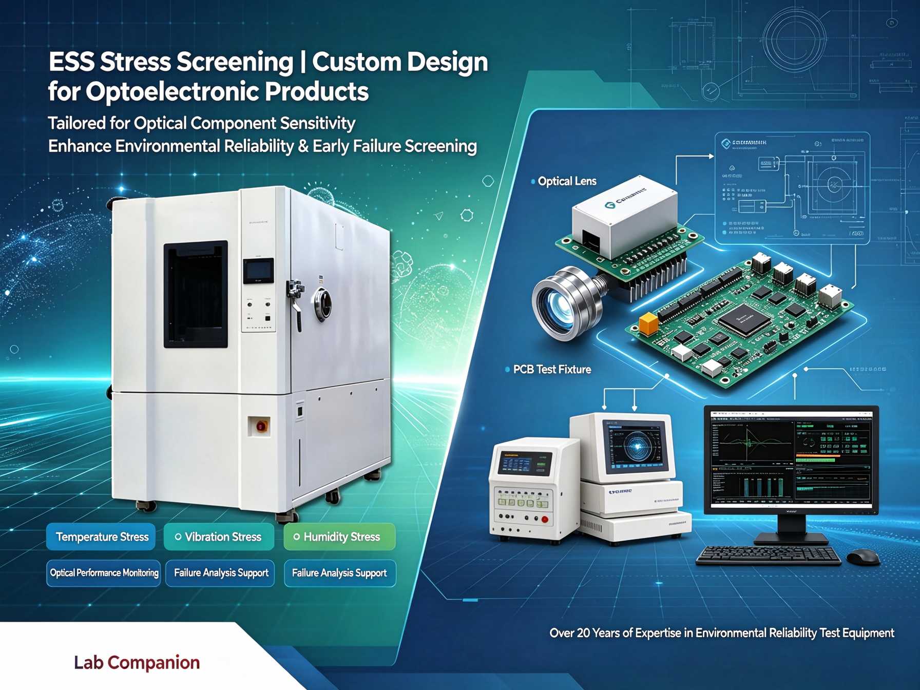
Power amplifiers generate substantial heat during operation, especially under high-power test conditions. Confirm that the cooling capacity and airflow can offset heat dissipation to avoid temperature runaway under loaded conditions. Sizing based only on passive components will fail active amplifier testing later.
Good performance at no load does not guarantee reliable full-load operation. Since RF parameters are extremely temperature-sensitive, request full-load multi-point temperature mapping data from the manufacturer. Where possible, run comparison tests with actual samples to confirm acceptable deviation across different mounting positions.
If in-situ RF measurement during thermal cycling is required, define port configuration and sealing solutions at the selection stage. Retrofit after equipment arrival often incurs high modification costs and delays projects.
RF qualification often runs continuously for long durations. Equipment stability directly impacts project schedules. Lab Companion operates three R&D and manufacturing bases in Dongguan, Kunshan and Chongqing, with over 6,000 ㎡ production space and an annual output of approximately 2,000 environmental test chambers. Our nationwide service network supports long-term reliable operation.
The reliability of RF devices is reflected in curves of frequency drift, insertion loss and VSWR versus temperature. Frequency offset, loss variation, solder joint fatigue and high-frequency dielectric drift all emerge under rapid thermal cycling. Lab Companion rapid thermal cycling chambers for RF devices combine wide temperature range, precise control and uniform thermal fields, helping RF enterprises obtain authentic and trustworthy temperature characteristic data. Going forward, Lab Companion will continue to deepen its expertise in environmental reliability testing, delivering stable test equipment to support R&D validation for RF and microwave products.
 見積もりを依頼する


 IPv6ネットワークをサポート