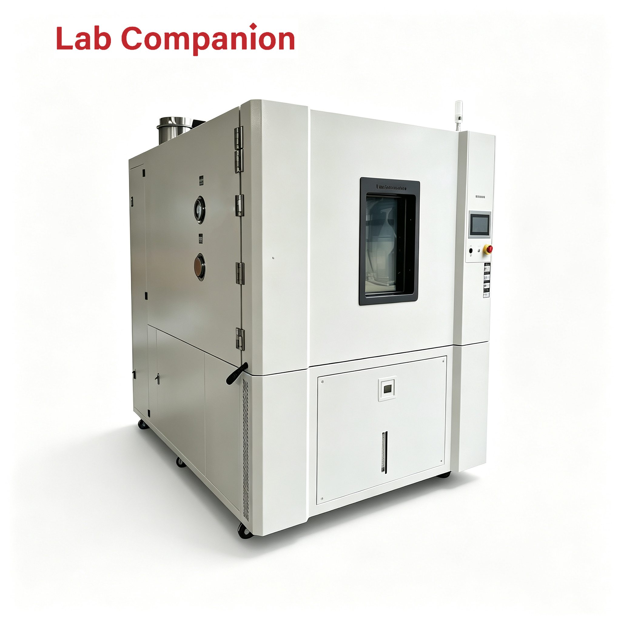
バナー
ホーム

温度環境試験室

温度環境試験室

  • LabCompanion OVEN Series High-Temperature Aging Chamber: Uniform & Controllable Temperature Field for Comparable Batch Test Results LabCompanion OVEN Series High-Temperature Aging Chamber: Uniform & Controllable Temperature Field for Comparable Batch Test Results
    Nov 13, 2026
    High-temperature aging serves as an independent, vital segment within the reliability validation framework. Reliability testing often starts with temperature cycling, yet many latent failures do not require temperature variation to surface. Examples include electrolyte volatilization in electrolytic capacitors, incomplete curing of molding compounds, slow corrosion from flux residues, and stress relaxation of connectors. These failure modes only emerge after prolonged exposure to constant high temperature and are difficult to detect solely via temperature cycling. Therefore, high-temperature aging stands alongside temperature cycling, humidity testing and vibration testing to form a complete reliability validation matrix. With over 20 years of expertise in environmental reliability test equipment, LabCompanion offers the OVEN Series high-temperature aging chambers to meet constant-temperature screening and material stabilization requirements. 1. Core Functions of High-Temperature Aging 1.1 Accelerate Early Failure Detection Electronic components and assemblies may contain latent defects introduced during manufacturing, such as cold solder joints, material inclusions and batch-to-batch material variations. These defects remain dormant at ambient temperature, while elevated temperatures accelerate chemical reactions and trigger failures in advance. After high-temperature aging for a specified duration, defective units are screened out, significantly improving the consistency of outgoing batches. 1.2 Material Stabilization & Stress Relief Materials including potting compounds, coatings and structural adhesives require sustained high-temperature exposure for full curing and internal stress release. Skipping this stabilization process before deployment will lead to shrinkage, cracking or degraded adhesion under subsequent temperature fluctuations. A high-temperature aging chamber delivers the controlled, stable constant thermal environment required for this process. 1.3 Division of Scope vs. Temperature Cycling Temperature cycling evaluates thermo-mechanical stress induced fatigue and cracking. High-temperature aging targets chemical and gradual physical changes driven by constant heat. Their failure mechanisms differ fundamentally and neither test can replace the other. A well-designed reliability program combines both test types for complementary validation. 2. Critical Performance Requirements for High-Temperature Aging Chambers 2.1 Temperature Uniformity at High Temperatures Heat transfer inside the chamber at high working temperatures relies mainly on convection and radiation, which easily create temperature gradients. Poor temperature uniformity causes uneven aging rates: samples near heating elements or air outlets age faster while units at chamber corners lag behind. Inconsistent aging across one batch undermines the validity of screening results. 2.2 Stability for Long Continuous Operation Aging cycles commonly run for tens to hundreds of hours. Long-duration operation exposes issues such as temperature control drift, heater degradation and fan bearing wear. Consistent temperature performance throughout the full aging cycle directly determines data reliability. 2.3 Ventilation & Safety Design Aging may release solvents, flux residues and thermal decomposition by-products. Insufficient ventilation allows hazardous gas accumulation, which contaminates test samples and creates safety risks. Adjustable air exchange rate, optimized exhaust routing, independent over-temperature protection and door interlock are key features that distinguish aging chambers from ordinary drying ovens. 2.4 Chamber Volume Matching for Energy Efficiency Continuous long-running operation makes energy consumption a major part of total ownership cost. Oversized chambers waste heat on empty space during every heating cycle. Selecting the right chamber size according to actual batch load and avoiding long-term underloaded operation is an effective way to cut operating costs. 3. LabCompanion OVEN Series High-Temperature Aging Chamber Solutions 3.1 Serialized Volume Options The OVEN Series covers multiple chamber sizes, supporting small-batch R&D validation as well as high-volume production screening. Users can select the proper model based on sample quantity and layout. There is no need to purchase an oversized chamber for low-volume testing or combine multiple small units to fulfill large-batch requirements. 3.2 Precise Temperature Control & Data Logging Temperature range: -70℃ ~ +150℃. At high-temperature settings, temperature fluctuation is ±0.3℃ and temperature deviation is ±2℃, meeting the aging specifications for most electronic components and assemblies. Temperature profiles and operation logs are automatically recorded. Start/end timestamps, real-time temperature readings and alarm events are fully traceable to support batch judgment and quality review. 3.3 Customization & Optional Safety Packages Aging workflows vary widely across industries. Custom options built on the standard platform include multi-layer trays, live-circuit aging feedthroughs, adjustable ventilation structures and customized exhaust layouts. LabCompanion is headquartered in Dongguan, with three R&D and manufacturing bases in Dongguan, Kunshan and Chongqing. The total production area exceeds 6,000 ㎡ and annual output reaches approximately 2,000 environmental test chambers. Service points are deployed across major regions of China for responsive local support. 4. Selection Guidelines 4.1 Calculate Required Volume Based on Samples & Batch Size When sizing the chamber, calculate according to total sample quantity and tray layout. Reserve clearances between layers and samples for smooth airflow. For powered aging, allocate extra space for fixtures and wiring to avoid under-sizing. Proper matching reduces unnecessary energy waste. 4.2 Verify Temperature Uniformity Under Full Load Empty-chamber uniformity only reflects the theoretical upper limit of the unit. Full-load temperature mapping data represents real working performance. Request full-load multi-point temperature test reports from the supplier during evaluation. Re-testing using your actual sample arrangement is strongly recommended. 4.3 Prioritize Safety Configuration & Maintainability For continuous high-temperature operation, over-temperature protection, door interlock, ventilation/exhaust and fault alarms are mandatory. Confirm service life, spare part availability and lead time for consumables including heaters, fans and seals in advance to prevent unexpected test interruption. Recommended practice: Formalize aging parameters into standardized SOPs, defining temperature, dwell time, loading rules and acceptance criteria. Save validated recipes in the chamber controller for one-click recall. This standardizes execution across shifts and operators and facilitates process iteration and root-cause analysis. Conclusion High-temperature aging measures the cumulative effect of heat and time. Consistent long-term equipment performance is the foundation of trustworthy screening results. The LabCompanion OVEN Series high-temperature aging chambers feature a wide -70℃ ~ +150℃ working range, a full lineup of chamber sizes, ±0.3℃ temperature stability and automatic data logging. Customization and safety upgrades are available. Backed by three manufacturing hubs and a nationwide service network, LabCompanion delivers proven constant-temperature aging solutions for electronic components and assemblies.
    続きを読む
  • Lab Companion – Thermal Cycling Test Chamber Supplier: Wide Temperature Range & Long-Term Stable Operation for Industrial Control Equipment Reliability Testing Lab Companion – Thermal Cycling Test Chamber Supplier: Wide Temperature Range & Long-Term Stable Operation for Industrial Control Equipment Reliability Testing
    Nov 11, 2026
    Industrial control equipment including PLCs, inverters, industrial sensors and control cabinets are widely deployed in factories, outdoor sites, oilfields, mines and other harsh environments. These products feature wide operating temperature range, non-stop service and high reliability requirements. Throughout their service life, they are exposed to day-night temperature swings, seasonal variations and load fluctuations. Cumulative thermal stress may lead to contact failure, parameter drift and performance degradation. Thermal cycling test chambers serve as essential equipment to verify the long-term reliability of industrial control equipment under wide temperature conditions. With over 20 years of expertise in environmental reliability test equipment, Lab Companion is a professional supplier of thermal cycling test chambers dedicated to the industrial control sector. 1. Unique Requirements of Thermal Cycling Testing for Industrial Control Products 1.1 Wide Temperature Range Evaluation Industrial control equipment operates across diverse locations and working conditions, from frigid winters in northern regions to extreme heat outdoors in the south. Thermal cycling tests must cover a broad temperature spectrum to validate product reliability at high and low temperature limits. 1.2 Long-Duration Continuous Cycling Test Industrial control equipment is designed for multi-year continuous operation. Thermal cycling testing uses numerous consecutive temperature cycles to accelerate the simulation of long-term environmental changes, which imposes strict demands on the sustained stability of test chambers. 1.3 Support for Both R&D Validation and Production Screening Manufacturers of industrial control products need reliability evaluation for new prototypes in the R&D phase as well as environmental stress screening for finished goods during mass production. The chambers shall accommodate both small-batch R&D tests and large-volume synchronous screening. 2. Key Specifications of Thermal Cycling Test Chambers for Industrial Applications 2.1 Wide Temperature Regulation Range To match various on-site industrial thermal conditions, the chamber’s temperature span must fully cover the rated operating limits of test samples and support compliance testing for different industrial projects. 2.2 Reliable Long-Running Performance Thermal cycling tests often run for hundreds of cycles without interruption. The refrigeration and heating systems must maintain consistent output without noticeable attenuation to prevent test stoppage and invalid data, securing stable testing schedules. 2.3 Superior Temperature Uniformity & Control Accuracy When multiple samples are loaded in one batch, temperature consistency across all positions inside the chamber is critical. It ensures identical test conditions for all units in the batch, comparable results and credible evaluation conclusions. 3. Lab Companion Thermal Cycling Test Chamber Solutions 3.1 Wide Temperature Coverage for Multiple Scenarios Standard models feature a temperature range of -70℃ ~ +150℃, covering the operating thermal envelope for most industrial control equipment and supporting high-low temperature cycling reliability assessment. 3.2 Durable System for High-Frequency Continuous Cycling The thermal systems have passed durability validation and can stably run hundreds of uninterrupted temperature cycles with steady performance, ideal for accelerated long-term reliability testing of industrial control products. 3.3 Precise Temperature Control for Batch Testing Temperature fluctuation: ≤ ±0.3℃; Temperature deviation: ≤ ±2℃. Multi-layer sample racks are optional to hold multiple industrial control units simultaneously, satisfying both R&D trials and mass production screening. 3.4 Automatic Data Logging for Traceability & Certification The chamber automatically records and exports full temperature profiles and test logs. Complete test records support quality traceability, third-party inspection and certification audits for industrial products. 4. Selection Guidelines 4.1 Select Temperature Range Based on Application Conditions Choose the chamber according to the high/low temperature limits of your actual deployment sites. Extended wide-range models are recommended for cold outdoor or extreme thermal applications. 4.2 Prioritize Long-Term Operating Stability Thermal cycling tests for industrial control equipment usually run continuously for extended periods. Do not judge the chamber solely by short-term single-point parameters; focus on performance retention under continuous cycling. 4.3 Partner with a Supplier with Rich Industrial Experience Reliability testing for industrial control products follows special procedures and standards. A supplier familiar with industry requirements can deliver well-matched chambers, commissioning service and after-sales support. Conclusion The core requirements of thermal cycling testing for the industrial control industry lie in wide temperature capability and stable long-duration operation. With over 20 years of focus on environmental reliability test equipment, Lab Companion supplies thermal cycling chambers featuring wide temperature coverage, durable stability, precise control and batch-test capability, helping industrial control manufacturers complete reliability validation and stress screening. Lab Companion will continue technological innovation to deliver robust and compliant environmental reliability test equipment for the industrial control sector.
    続きを読む
  • Lab Companion -40°C Temperature Cycling Chamber | Batch Testing for Automotive & Industrial Screening Lab Companion -40°C Temperature Cycling Chamber | Batch Testing for Automotive & Industrial Screening
    Nov 06, 2026
    -40°C is a widely adopted low-temperature limit for reliability temperature cycling tests. Automotive electronics, industrial control modules and outdoor communication products must withstand drastic temperature changes to verify their resistance to thermal stress across a wide temperature range. With over 20 years of expertise in environmental reliability test equipment, Lab Companion offers this -40°C temperature cycling chamber tailored to temperature cycling screening requirements under automotive and industrial standards. 1. Applicable Industries 1.1 Automotive Electronics Automotive components operate under alternating high and low temperatures. Cold start performance is a critical test item, and -40°C serves as the standard low-temperature limit for temperature cycling tests, validating component stability under thermal cycling. 1.2 Industrial Control Industrial control equipment is deployed in factories and open-air sites with broad operating temperature ranges. Temperature cycling tests covering -40°C assess the reliability of mainboards and drive modules in low-temperature conditions. 1.3 Outdoor & Communication Equipment Base stations and outdoor terminals are exposed to seasonal temperature swings. -40°C cycling simulates severe winter conditions to verify long-term durability for field deployment. 2. Key Performance Criteria 2.1 Low-Temperature Steady Cooling Capacity Reliably cooling from ambient down to -40°C and maintaining set temperature is fundamental for cycling tests. The refrigeration system ensures stable low-temperature hold to complete the full temperature profile. 2.2 High-Low Temperature Transition Performance Cycling requires repeated switching between -40°C and high-temperature setpoints. The chamber delivers smooth temperature transitions, faithfully following programmed profiles and avoiding excessive overshoot that compromises test validity. 2.3 Temperature Uniformity & Control Accuracy Consistent chamber conditions are essential when testing batches of samples. Superior temperature uniformity and precision guarantee identical test conditions for all specimens, enabling comparable and trustworthy results. 3. Lab Companion Chamber Advantages 3.1 Stable Cooling at -40°C Standard models cover a temperature range of -70°C ~ +150°C. Stable cooling and reliable temperature holding at -40°C fully meet low-temperature cycling requirements for mainstream automotive and industrial specifications. 3.2 Smooth Cycling with Minimized Temperature Overshoot Repeated transitions between -40°C and high temperatures follow a smooth, controllable profile with reduced overshoot to keep tests compliant with defined specifications. 3.3 Multiple Ramp Rates & Precise Control Selectable ramp rates: 5°C/min, 10°C/min, 15°C/min. Temperature fluctuation ≤ ±0.3°C, temperature deviation ≤ ±2°C. High control accuracy is maintained across both low and high temperature zones. 3.4 Batch Testing & Traceable Test Data Multi-layer sample racks are available for simultaneous cycling of multiple test pieces. Temperature profiles and logs are automatically saved to support quality control and full data traceability. 4. Selection Guidelines 4.1 Define Low-Temperature Limit Based on Test Standards Check your product specification first. If only -40°C testing is required, choose a matching model to optimize cost. Select a wider-range chamber if lower-temperature testing may be needed for future projects. 4.2 Prioritize Low-Temperature Steady-State Performance Do not rely solely on the labeled temperature range. Verify cooling stability and long-duration hold performance at -40°C under continuous cycling to ensure genuine and controllable test conditions. 4.3 Consider Long-Term Reliability & After-Sales Support Temperature screening often runs nonstop for extended periods. Select an established manufacturer with mature production and nationwide service networks to support reliable equipment operation throughout its lifecycle. Conclusion The -40°C temperature cycling chamber is essential reliability screening hardware for automotive electronics, industrial control and communication products. Drawing on decades of experience in environmental test equipment design and manufacturing, Lab Companion delivers chambers featuring stable low-temperature performance, smooth thermal cycling, flexible ramp rates and precise control. We provide robust temperature cycling solutions for automotive and industrial reliability validation. Lab Companion keeps innovating to deliver high-performance test equipment for reliability engineering worldwide.
    続きを読む
  • Lab Companion Compact Rapid Thermal Cycling Chamber Lab Companion Compact Rapid Thermal Cycling Chamber
    Nov 04, 2026
    Space-saving & Energy-efficient, Ideal for Laboratories and On-site Testing Value of Compact Rapid Thermal Cycling Chambers For R&D labs, low-volume pilot production and quality inspection, many companies do not require large-volume thermal cycling chambers. Instead, they prefer compact, flexible and user-friendly test equipment. Our compact rapid thermal cycling chamber delivers full thermal cycling reliability performance in a small footprint, perfectly catering to testing of small samples and low-batch runs. With over 20 years of expertise in environmental reliability test equipment, Lab Companion develops compact rapid thermal cycling chambers to serve R&D laboratories and low-volume production testing. 1. Application Scenarios 1.1 R&D Laboratory Validation Prototypes and small samples go through frequent iterations in the R&D phase and require repeated thermal cycling tests. This compact unit can be placed directly on lab benches for immediate testing, greatly accelerating R&D verification. 1.2 Stress Screening for Low-volume Pilot Runs Sample quantities are limited during new product pilot production. Large chambers run at low utilization and incur high energy costs. The compact rapid thermal cycling chamber handles stress screening for small batches independently, cutting capital investment and operational costs. 1.3 On-site & Off-line Inspection It can be deployed beside production lines or inspection stations for spot checks. Flexible placement eliminates the need to send samples to a central test room and speeds up quality response. 2. Key Specifications 2.1 Full Temperature Range & Ramp Rates, No Performance Compromise Small in size but equivalent to large chambers in core testing capability. The standard compact rapid thermal cycling chamber covers -70℃ to +150℃, with selectable ramp rates of 5℃/min, 10℃/min and 15℃/min to meet thermal cycling reliability requirements for electronic components and assemblies. 2.2 Stable & Precise Temperature Control Small cavities have low thermal mass and are prone to temperature fluctuations. Optimized control algorithms and air duct design deliver temperature fluctuation ≤ ±0.3℃ and temperature deviation ≤ ±2℃, maintaining consistent thermal conditions and repeatable test results. 2.3 Small Footprint & Low Power Consumption It occupies minimal floor space and draws less power, with lower requirements for lab layout and electrical supply — perfect for space-constrained R&D and inspection areas. 3. Lab Companion Solution Highlights Compact Design, Uncompromised Performance: Built in a space-saving layout with -70℃ ~ +150℃ working range and multiple ramp rate options, matching the reliability test capacity of larger chambers. Uniform Thermal Field for Trustable Data: Advanced temperature control offsets cavity disturbance common in small chambers and ensures stable, consistent test outcomes. Intuitive Operation & Traceable Records: Simple HMI for fast test program setup and recall. The system automatically logs temperature profiles and test data to support R&D archiving, quality traceability and audit compliance. 4. Selection Guidelines Select based on sample size and batch quantity: Evaluate chamber volume according to sample dimensions, loading capacity and available workspace. Compact models are recommended for R&D and spot inspection to avoid waste of space and power from over-sized equipment. Verify core performance parameters: Many compact chambers on the market reduce temperature range, ramp speed or temperature accuracy. Confirm working range, ramp rate, fluctuation and deviation to ensure compliance with your test standards. Consider long-term stability and service support: Compact test chambers also require reliable operation and routine maintenance. Choose an established manufacturer with mature production and nationwide service networks to secure full-lifecycle support. Conclusion Compact rapid thermal cycling chambers solve key pain points for R&D and low-volume quality testing through small footprint and flexible deployment, without sacrificing core reliability performance. Lab Companion specializes in environmental reliability test equipment. Our compact rapid thermal cycling chamber combines space efficiency, wide temperature range, multiple ramp rates, precise temperature control and easy operation to support efficient R&D validation and small-batch stress screening. Moving forward, Lab Companion will keep innovating to deliver more flexible and reliable thermal cycling test solutions for global industries.
    続きを読む
  • Lab Companion Rapid Temperature Cycling Chamber for OCS Optical Circuit Switches: Multi-Step Linear Temperature Ramp Rates Safeguard Optical Switching Networking for AI Clusters Lab Companion Rapid Temperature Cycling Chamber for OCS Optical Circuit Switches: Multi-Step Linear Temperature Ramp Rates Safeguard Optical Switching Networking for AI Clusters
    Oct 27, 2026
    I.Industry Background and Thermal Cycling Challenges of OCS Optical Circuit Switches 1. Large-Scale Deployment of OCS Accelerates OCS (Optical Circuit Switch) establishes physical optical paths directly between fiber ports without electrical conversion. Compared with electrical switches, it features low power consumption, protocol transparency, and reconfigurable topology. It is evolving from proprietary solutions used by a small number of cloud vendors into networking infrastructure widely adopted by AI clusters. According to industry forecasts, the OCS market will maintain robust growth in the coming years. Optical switching equipment has become a key enabler for the evolution of AI computing networks. As deployment scales up, long-term reliability of optical switches under complex data center environments has drawn shared attention from equipment manufacturers and cloud operators. 2. Why Optical Switching Equipment Is Highly Sensitive to Temperature Variations The core performance of optical switching relies on precise optical alignment. Low-loss optical signal routing across ports depends on the spatial alignment accuracy of optical components inside the light path. Unlike electrical switches that transmit stable electrical signals, optical alignment is extremely vulnerable to minor structural deformation. Temperature fluctuations trigger thermal expansion and contraction of the enclosure, optical base, micromirror array and other structures. Even micron-level displacement can lead to higher insertion loss, increased crosstalk, or complete optical path mismatch. Therefore, temperature conditions are a critical factor in reliability validation for optical switching hardware. II. Typical Failure Mechanisms of OCS Devices 1. Thermal Drift of Optically Aligned Components OCS integrates movable micromirror arrays and collimating optical assemblies to switch optical paths between ports. These components suffer thermal drift under temperature changes: material expansion or contraction shifts mirror angles and light spot positions, reducing optical coupling efficiency. After repeated temperature cycles, accumulated offset may result in permanent structural deformation and gradual performance degradation over service life. 2. Thermal Strain and Progressive Optical Performance Degradation Fixed mechanical structures also endure thermal stress during temperature cycling. The housing, optical substrate and fasteners are made of dissimilar materials with different coefficients of thermal expansion. Mechanical stress builds up under temperature variation, which may eventually cause loose assembly, alignment drift and connector fatigue. This type of failure rarely causes immediate service outage. It usually manifests as rising insertion loss and higher bit error rate. Such latent defects are easy to overlook yet severely compromise the overall reliability of optical switches. III. Standards for Temperature Cycling Testing 1. Telecom-Grade Environmental Requirements per GR-468-CORE Reliability testing for optical communication components generally follows Telcordia GR-468-CORE, which specifies reliability assurance requirements for optoelectronic devices. Temperature cycling is one of the mandatory test items. GR-468 defines multiple test grades. The standard test profile covers -40℃ to +85℃ with a minimum of 500 cycles. For enhanced structural durability verification, test profiles such as -40℃ to +70℃ with 100 or 500 cycles are commonly adopted, with strict specifications on temperature ramp rate and dwell time. 2. Two Core Criteria for Valid Temperature Cycling Tests The validity of temperature cycling hinges on two key factors: stable and controllable ramp rates, and uniform temperature distribution inside the chamber. Excessively fast or non-linear ramping introduces unexpected thermal shock and distorts test results. Poor temperature uniformity creates inconsistent thermal stress across samples in the same batch, undermining screening and validation. For high-precision optical devices such as OCS, the test chamber must deliver stable linear temperature ramping and superior temperature uniformity across a wide working range. IV. Lab Companion Rapid Temperature Cycling Chamber Solution for OCS 1. Key Specifications Lab Companion rapid temperature cycling chambers are purpose-built for reliability validation of optoelectronic devices and high-reliability electronic products. Temperature range: -70℃ ~ +150℃. Fully covers the standard -40℃ ~ +85℃ telecom grade range defined in GR-468-CORE, with extra margin for extended testing from -55℃ ~ +125℃. Temperature stability: Fluctuation ≤ ±0.5℃, temperature deviation ≤ ±2℃ for consistent control throughout tests. Temperature ramp rates: 5℃/min, 10℃/min, 15℃/min, 20℃/min, 25℃/min are available as standard. Both linear and non-linear modes are supported. Custom linear ramp rates from 5℃/min to 20℃/min are offered for the core -40℃ ~ +85℃ range, with linearity controlled within ±1℃/min. Valid ramp range: -55℃ ~ +125℃, meeting most validation requirements for optical switching components. Optional humidity control: Humidity range 20 ~ 98% RH for standard models; low-humidity version reaches 5 ~ 98% RH. Humidity deviation: ±3.0% RH (below 75% RH), ±5.0% RH (≥75% RH). 2. Customized Testing Adaptation for OCS To address the stringent requirements of OCS optical switches on ramp linearity and temperature uniformity, the chamber adopts linear smooth temperature control to avoid unintended thermal shock on samples. Configurations range from standard benchtop chambers to custom walk-in chambers, supporting validation from discrete optical components to full OCS units. The system supports programmable multi-segment temperature profiles and automatic data logging. Test engineers can correlate temperature cycle records with optical metrics including insertion loss, crosstalk and BER for failure analysis. V. Conclusion Rigorous temperature cycling validation is indispensable for mass production and stable long-term operation of OCS optical circuit switches. Lab Companion rapid temperature cycling chambers deliver wide temperature range, configurable multi-grade linear ramp rates and consistent thermal uniformity. They provide full-lifecycle reliability support for OCS hardware deployed in AI clusters, from R&D characterization to production screening, complying with GR-468-CORE standards and stabilizing optical switching networks for computing infrastructure.
    続きを読む
  • Lab Companion | ESS Stress Screening for Optoelectronic Products: Linear & High-Precision Temperature Ramp to Secure Optical Performance Lab Companion | ESS Stress Screening for Optoelectronic Products: Linear & High-Precision Temperature Ramp to Secure Optical Performance
    Oct 26, 2026
    Optoelectronic products such as optical modules and optical assemblies require both stable optical performance and electronic reliability. Their failures often manifest as optical performance degradation alongside structural defects. Environmental Stress Screening (ESS) before mass delivery is critical to weed out early failures and guarantee consistent optical performance. Given the high sensitivity of optical components to thermal disturbance, the ESS screening plan for optoelectronic products cannot be directly adopted from that for ordinary electronic devices. Rooted in the intelligent manufacturing base in Dongguan, Lab Companion has specialized in environmental reliability test equipment for over two decades. We provide tailored ESS stress screening solutions for the optical communication and optics industries. This article starts with failure mechanisms and outlines key considerations for ESS screening of optoelectronic products. 1. Typical Failure Mechanisms of Optoelectronic Products 1.1 Optical Performance Is Vulnerable to Thermal Stress The optical engine is highly sensitive to temperature changes. Thermal stress triggers wavelength shift and optical power fluctuation, directly degrading signal transmission quality. This is the core difference between optoelectronic devices and pure electronic components. 1.2 Thermal Fatigue of Interconnections and Packaging Lasers, photodetectors and high-speed circuits feature intricate interconnection structures. Under temperature cycling, mismatched Coefficients of Thermal Expansion (CTE) among different materials accumulate thermo-mechanical stress, which easily causes solder joint fatigue and package cracking. 1.3 Misalignment of Optical Paths and Microstructure Instability Optical assemblies rely on micron-level alignment precision. Deformation induced by temperature variation leads to optical misalignment and microstructure damage, which reduces optical indicators. Such damage is often latent and hard to detect in advance. 2. Core Requirements for ESS Screening of Optoelectronic Products 2.1 Linear and Controlled Temperature Ramp to Avoid Misjudgment of Optical Performance ESS for optoelectronics demands smooth temperature transition. Temperature overshoot and internal condensation must be prevented. Temperature overshoot instantly disturbs key indicators including optical power and wavelength; condensation corrodes optical end faces and circuits, introducing non-genuine failures and skewing screening results. Steady and linear temperature ramp is the foundation of optoelectronic ESS. 2.2 Compliance with Authorized Industry Specifications Reliability screening for optical communication components generally follows standards such as GR-468-CORE. Clear requirements are defined for temperature range, ramp rate, cycle count and dwell time. Equipment specifications must meet these standard requirements. 2.3 Adaptation to Mass Production Screening The optical communication industry features large shipment volumes. Production-line ESS needs simultaneous testing of multiple devices. The equipment shall support batch loading to match production tact time and improve screening coverage and efficiency. 3. Lab Companion ESS Stress Screening Solution for Optoelectronics 3.1 Wide Temperature Range with Multiple Linear Ramp Rates Standard models cover a temperature range from -70℃ to +150℃, with optional ramp rates of 5℃/min, 10℃/min and 15℃/min to suit different screening specifications for optical devices. 3.2 High-Precision Temperature Control and Uniform Thermal Field Temperature fluctuation ≤ ±0.3℃, temperature deviation ≤ ±2℃. Excellent internal thermal consistency ensures all samples in the same batch are exposed to identical thermal stress, delivering comparable and repeatable screening results. 3.3 Batch Loading & Full-Process Data Traceability Multi-layer sample racks are available for simultaneous testing of large batches of optoelectronic devices. The system automatically archives temperature profiles and test logs to satisfy quality control and traceability compliance requirements in the optical communication industry. 3.4 Flexible Customization Customizable chamber volume, temperature ramp rate, independent thermal zones and external data acquisition interfaces are available according to product dimensions and test conditions, catering to diverse test demands of optical modules and optical assemblies. 4. Equipment Selection Guide for Mass-Production ESS 4.1 Define Screening Parameters against Standards Determine the temperature range, ramp rate and cycle count based on specifications such as GR-468-CORE. Select equipment with adequate performance margin instead of operating continuously at full load. 4.2 Prioritize Linear Ramp and Anti-Condensation Performance Optoelectronic devices are sensitive to thermal shock. Focus on evaluating linear temperature ramp capability, anti-condensation design and thermal uniformity to avoid misjudgment caused by abnormal thermal disturbance. 4.3 Match Loading Configuration with Production Capacity For mass screening, prioritize models compatible with multi-layer racks and suitable chamber size to match production output and maximize sample quantity per test run. 4.4 Full-Cycle Technical Support Choose manufacturers with in-house manufacturing capacity and a sound service network. Reliable support covering installation, commissioning and calibration helps smooth the verification process for mass production of optoelectronic products. Conclusion The reliability of optoelectronic products stands for dual stability of optical performance and electronic structures. Based in Dongguan, Lab Companion delivers ESS stress screening solutions featuring wide temperature range, high-precision linear temperature ramp, stable thermal field, batch testing and full traceability, safeguarding the long-term stable operation of optical devices. Going forward, Lab Companion will keep focusing on environmental reliability test equipment and continuously empower reliability upgrading of the optical communication and optics industries.
    続きを読む
  • Lab Companion Temperature Cycling Chamber for Router Modules: Equipment Solution for Full-Link Temperature Cycling Validation of Network Devices
    Oct 17, 2026
    I. Why Router Modules Require Temperature Cycling Testing 1.1 Mechanism of Temperature Variation Impact on Signal Transmission Quality As the core unit for network data forwarding, router modules integrate switching chips, network processors, PHY chips, high-speed differential signal traces and various passive components. The core objective of temperature cycling testing for router modules is not merely verifying basic power-on functionality, but maintaining acceptable signal integrity throughout the test. High-speed differential links within router modules are highly sensitive to temperature fluctuations. During temperature cycling, thermal expansion and contraction of PCB substrates and chip packages cause minor shifts in trace impedance, degrading eye diagram performance and reducing timing margin. For Wi-Fi 6/7 wireless router modules, the gain of power amplifiers and noise figure of low-noise amplifiers in the RF front-end drift with temperature, directly resulting in fluctuating wireless throughput and elevated packet loss rate. Temperature cycling simulates operating conditions under alternating high and low temperatures to assess module performance stability and functional reliability. It effectively activates early defects introduced by soldering processes and component batch variations. 1.2 Standard Basis for Router Module Temperature Cycling Testing Temperature cycling tests on router modules comply with multiple leading international and Chinese standards, including GB/T 2423.22, IEC 60068-2-14, MIL-STD-810G and ETSI EN 300 019. These specifications define clear requirements for test conditions, procedures, duration and temperature ramp rates. Certain router product certifications mandate environmental adaptability tests under temperature cycling conditions of -40°C to +85°C with 95%RH non-condensing humidity. During testing, samples must remain powered on while key metrics such as throughput, packet loss rate and signal strength are monitored in real time to verify communication stability under changing thermal conditions. 1.3 In-line Monitoring: Core Requirement for Router Temperature Cycling Testing Temperature cycling for router modules differs fundamentally from discrete component testing. Component testing only evaluates parameter recovery after thermal exposure. As fully functional network units, router modules must sustain continuous traffic forwarding throughout the thermal cycle. Even if functionality recovers once temperature returns to normal, any mid-test throughput drop, rising packet loss or temporary disconnection indicates temperature-related latent failure risks. Therefore, temperature cycling chambers for router modules must feature in-line monitoring ports to keep samples powered inside the chamber and capture real-time throughput, bit error rate and other performance data via external test instruments. II. Key Technical Requirements for Router Module Temperature Cycling Chambers 2.1 Superior Temperature Uniformity to Ensure Consistency in Multi-Module Testing Router modules are frequently tested in batches with multiple samples loaded simultaneously. Significant temperature variance across the chamber cavity would expose samples to inconsistent thermal stress and invalidate result comparability. Lab Companion adopts dual air duct circulation and multi-point sensor layout. Under full-load operation, temperature uniformity is controlled within ≤±2.0°C, temperature fluctuation ≤±0.5°C with temperature deviation of ±2°C. This specification ensures uniform thermal stress applied to samples placed at different positions in one batch, delivering comparable and repeatable data for batch screening and sampling inspection. 2.2 Anti-Condensation Design & In-line Monitoring Cable Ports Router modules operate powered-on inside the chamber. Condensation may form on component pins and PCB surfaces during temperature recovery from low temperature, leading to short circuits of test cables and distorted measurement readings. Lab Companion, a China-based manufacturer, implements systematic anti-condensation solutions covering airflow organization, humidity regulation and chamber structural design. The viewing window uses hollow coated electrically heated glass to prevent condensation at low temperatures. Dedicated electrical cable feedthrough ports are reserved on the chamber to route test cables outside, supporting continuous powered operation and real-time performance monitoring of samples. 2.3 Stable Temperature Control for Signal Integrity under Cycling Conditions Router modules are sensitive to ambient temperature disturbances. Throughput may degrade even when port indicators remain normal. The chamber shall provide stable temperature plateaus to minimize extra test errors introduced by control fluctuations. Lab Companion uses balanced PID temperature regulation combined with fuzzy logic control algorithms to sustain stable thermal conditions during long-duration continuous cycling tests. III. Complete Temperature Cycling Solution from Lab Companion (China) 3.1 Brand Background & Manufacturing Bases Founded in 2005 and headquartered in Dongguan, Guangdong, China, Lab Companion is a Chinese National High-Tech Enterprise and Guangdong Provincial Specialized, Refined, Differential & Innovative Enterprise. With over 20 years of expertise in environmental reliability test equipment, the company operates under ISO9001, ISO14001, ISO45001 and ISO27001 management systems, and its products carry EU CE certification. Lab Companion runs three R&D and manufacturing facilities across China: Dongguan, Kunshan and Chongqing. The Dongguan headquarters serves as the R&D hub and main production site for standard models, covering a plant area of 27,286 m² with an annual output of around 1,000 environmental test chambers. 3.2 Temperature Range & Ramp Rate Options Lab Companion TC series rapid temperature cycling chambers feature a standard temperature range of -70°C to +150°C, expandable up to +180°C. The range fully meets requirements from GB/T 2423.22, IEC 60068-2-14 and covers the typical industrial-grade test envelope of -40°C ~ +85°C for router modules. Five ramp rate options are available: 5°C/min, 10°C/min, 15°C/min, 20°C/min and 25°C/min. Both linear and non-linear temperature profiles are supported to match ramp requirements from different certification standards. 3.3 In-line Monitoring Ports & Powered Test Configuration For powered temperature cycling of router modules, dedicated electrical feedthrough ports can be configured. Modules inside the chamber connect to external traffic testers and maintain packet forwarding during cycling. Throughput, packet loss rate and signal strength are captured in real time. Multi-channel temperature acquisition can be extended to synchronously monitor the temperature of core chips on modules. 3.4 Multiple Chamber Volumes & Customization Capability TC series chambers are offered in standard volumes: 34L, 64L, 100L, 180L, 340L, 600L and 1000L. Models of 80L, 150L, 225L, 408L and 800L are in stock. Custom sizes ranging from 80L up to 8000L are available. For batch testing of small-to-medium router modules, chamber size can be selected according to sample loading quantity. In-line performance monitoring projects can be equipped with cable feedthrough and anti-condensation packages upon request. 3.5 Intelligent Control System & Full Data Logging Equipped with self-developed C100 PID temperature & humidity controller integrated with fuzzy logic algorithm and a color touchscreen, the system supports multi-segment programming, automatic data logging and report generation. Temperature profiles, actual ramp rates, dwell durations and alarm logs are recorded in standardized format and exportable after tests, supporting report compilation and batch traceability. Built-in multi-layer safety protections including over-temperature protection, compressor overload protection and fan fault alarm ensure stable operation for long unattended thermal cycling runs. IV. Typical Application Scenarios Throughput Validation for Wi-Fi Routers RF component gain and noise figure drift under temperature variation for Wi-Fi 6/7 devices and cause wireless throughput fluctuation. The TC series performs temperature cycling in accordance with IEC 60068-2-14 and GB/T 2423.22. Samples stay powered on while external testers continuously record throughput to verify wireless performance stability under thermal cycling. Packet Loss Testing for Enterprise Routers Packet loss rate is a key reliability metric for enterprise routers. TC series chambers reserve cable feedthrough ports to connect in-chamber modules to external traffic testers for real-time monitoring of packet loss and transmission latency. Extended multi-channel temperature sensing supports parallel testing of multiple router units. Temperature Cycling Stress Screening for Switch Modules Switch modules share similar temperature cycling requirements with router modules. The excellent temperature uniformity of TC series ensures identical thermal stress applied on all samples, delivering repeatable results for batch screening. Reliability Validation for IoT Gateway Modules IoT gateways typically require wide operating temperature tolerance. With wide temperature range and controllable linear ramp capability, TC series reproduces thermal stress to evaluate temperature adaptability of gateway modules. V. Equipment Selection Guidelines 5.1 Temperature Uniformity for Multi-Station Parallel Testing For multi-sample concurrent testing, prioritize full-load temperature uniformity. TC series achieves ≤±2.0°C uniformity under full load to guarantee consistent stress exposure. Evaluate cavity temperature field distribution based on sample quantity and layout during selection. 5.2 In-line Monitoring Ports and Anti-Condensation Design Router temperature cycling usually requires powered operation. Confirm anti-condensation solutions and cable feedthrough availability during selection to avoid condensation-induced short circuits during low-temperature recovery. If real-time throughput and packet loss monitoring are required, define interface types and data formats of external instruments at procurement stage. 5.3 Chamber Volume and Fixture Compatibility Calculate required cavity volume based on module dimensions and batch loading quantity. Reserve extra space for cable routing for powered tests. For multi-layer rack testing of multiple units, check rack load capacity and ensure airflow is not blocked. 5.4 Standard Compliance and Test Data Traceability TC series chambers comply with IEC 60068-2-14, GB/T 2423.22 and other mainstream test standards. For certification projects, built-in data logging fully retains thermal profiles to support audit and traceability. VI. Conclusion The core challenges of temperature cycling testing for router modules lie in preserving signal integrity under powered operation, uniform thermal field control across multi-station setups, and stable performance during long continuous cycling. Manufactured by Lab Companion from China, the TC series rapid temperature cycling chambers deliver a -70°C ~ +150°C wide temperature envelope, 5~25°C/min adjustable ramp rates, ≤±0.5°C temperature fluctuation and ≤±2.0°C full-load uniformity. Combined with systematic anti-condensation solutions, in-line cable feedthrough ports and self-developed C100 control system, the chambers provide full-link reliability temperature cycling validation for Wi-Fi routers, enterprise routers, switch modules and IoT gateway modules. Technical specifications and custom configurations can be further discussed according to project test requirements.
    続きを読む
  • Lab Companion Custom Thermal Cycling Chamber: Customization Path for Temperature Range, Internal Volume & Dimensions, Temperature Ramp Rate and Special Functions
    Oct 16, 2026
    I. Necessity of Non-Standard Customization 1.1 Performance Limits of Standard Models Thermal cycling chambers serve as core equipment for reliability testing in electronics, semiconductors, automotive electronics, new energy and other industries. Lab Companion TC series standard thermal cycling chambers feature a standard temperature range of -70℃ to +150℃, with 5 selectable temperature ramp rates from 5℃/min to 25℃/min. Available internal volumes range from 34L up to 16,000L. Popular standard sizes including 80L, 150L, 225L, 408L and 800L are kept in stock. These configurations meet most conventional thermal cycling test requirements. Nevertheless, standard models have inherent performance boundaries. They cannot directly support test tasks when test specimens exceed the inner chamber size, when required test temperature limits go beyond the standard range, when samples need power-on operation or connection to data acquisition systems, or when tests involve flammable and explosive specimens requiring special protection. 1.2 Practical Scenarios for Non-Standard Customization Non-standard customization is not an optional add-on, but a prerequisite to valid testing execution. Typical application scenarios are listed below: New energy vehicle battery pack testing: full battery packs require testing covering -40℃ cold start and 85℃ high-temperature cycling; Semiconductor chip testing: demand for infinitely adjustable ramp rates from 1℃/min to 20℃/min to match different phases of chip testing; High heat-load testing: operating samples may generate heat up to tens of kilowatts. Standard chambers lack sufficient cooling capacity to maintain specified ramp rates under loaded conditions. Founded in 2005 and headquartered in Dongguan, Guangdong, Lab Companion is a National High-Tech Enterprise and Guangdong Provincial Specialized & Sophisticated Enterprise. With over 20 years of expertise in environmental reliability test equipment, we operate three R&D and manufacturing bases in Dongguan, Kunshan and Chongqing. We have established a full-cycle customization system covering requirement evaluation, design, production and delivery. II. Four Core Customization Dimensions for Lab Companion Thermal Cycling Chambers 2.1 Temperature Range Customization The baseline temperature range of standard TC chambers is -70℃ ~ +150℃. For aerospace and other special test applications, the low limit can be extended down to -100℃, while the upper temperature limit can reach +250℃. We have delivered proven custom units with a precise range of -78℃ ~ +150℃ to comply with GJB 150.5A military environmental test specifications. For combined temperature & humidity testing, integrated solutions covering 20%RH ~ 98%RH are available. 2.2 Internal Volume & Dimension Customization Chamber size is the most frequently requested custom item. Custom volumes from 80L to 8,000L can be engineered as requested. Our walk-in chambers start at 1,000L up to 10,000L, with further scaling available upon request. Inner chamber design takes full account of specimen outer dimensions, loading arrangement (single / multiple samples), material access methods (handcart, forklift, hoisting) and requirements for powered sample testing. Lab Companion once delivered a 20m³ extra-large custom chamber for an aerospace research institute to solve reliability testing challenges for large aerospace assemblies. Note: Standard models of 80L, 150L, 225L, 408L and 800L are in stock. 2.3 Temperature Ramp Rate Customization Standard chambers offer 5 fixed ramp rates: 5, 10, 15, 20 and 25℃/min. Customised ramp profiles can be developed per test specifications. For semiconductor projects, we have realised infinitely adjustable ramp rates from 1℃/min to 20℃/min to accommodate varied heating/cooling requirements across chip test phases. 2.4 Special Function Customization Optional dedicated functions can be integrated according to test workflows: Semiconductor applications: Nitrogen purge to prevent condensation on samples at low temperatures; High heat-load applications: dedicated thermal load matching solution to stabilise ramp rates under loaded conditions; Control & communication: RS485 and Ethernet as standard; optional OPC UA and Modbus TCP for MES connection. For semiconductor production lines, SECS/GEM protocol can be customised to enable seamless data exchange between test chambers and factory management systems; Additional options: remote monitoring, probe station interfaces and integrated data acquisition systems. III. Delivery Workflow from Requirement to Commissioning 3.1 In-depth Requirement Analysis & Technical Alignment The project starts with multiple rounds of technical discussion. Our engineers identify not only what needs testing, but also test purposes and acceptance targets. Combining test standards, specimen characteristics, test cycles and on-site factory conditions, we translate customer requirements into quantifiable technical specifications. 3.2 Concept Design & Proposal Confirmation Preliminary equipment design is generated based on requirement analysis. Core parameters to be finalised include temperature range, ramp rate profile, inner chamber dimensions, structural layout, fixture & electrical interfaces and control system functions. The proposal will undergo technical review and confirmation with customers to ensure equipment specifications fully match test demands. 3.3 Manufacturing & Factory Acceptance Testing Once the proposal is approved, production commences. Our three manufacturing bases achieve an annual capacity of more than 2,000 units. Standard models are delivered within 7–15 working days, while non-standard custom chambers can be finished within 20 working days. Before shipment, both no-load and loaded performance verifications are completed. 3.4 On-site Acceptance & Operational Training After equipment arrival, we perform installation, commissioning and on-site acceptance. Acceptance items cover temperature range and ramp rate under no-load conditions, ramp stability under loaded conditions, temperature uniformity & fluctuation, program cycle validation, communication and data acquisition verification. We also provide on-site operation training and maintenance support to secure long-term stable operation. IV. Manufacturing & Service Capabilities for Custom Thermal Cycling Chambers 4.1 Production Capacity at Dongguan Manufacturing Base The Dongguan headquarters serves as our R&D centre and primary production site for TC series chambers, with a plant area of 27,286 m² and an annual output of around 1,000 environmental test chambers. Products hold EU CE certification. Supported by the complete supply chain in the Greater Bay Area, R&D, component procurement, assembly and factory calibration are completed locally to shorten lead times. 4.2 Nationwide Service Network Sales and after-sales service centres are located in Beijing, Shanghai, Wuhan, Chengdu, Chongqing, Xi’an and Hong Kong, forming a nationwide service network with fast response for customers in the Pearl River Delta. The company operates under ISO9001, ISO14001, ISO45001 and ISO27001 management systems. The Lab Companion trademark is registered under the Madrid System, with trademark protection across 27 EU member states, UK, Canada and multiple Southeast Asian countries. 4.3 Core Hardware & Control System TC series chambers adopt cascade refrigeration with compressors from top international brands. Lab Companion’s proprietary cold balance energy-saving control technology eliminates energy waste caused by conventional simultaneous heating and cooling conflict. The controller is our self-developed C100 PID + fuzzy logic temperature & humidity control system, equipped with a colour touchscreen. It supports multi-segment programming, automatic data logging, report generation, network connection, remote monitoring and cluster management. V. Selection & Acceptance Guidelines for Non-Standard Custom Chambers 5.1 Technical Agreement Confirmation The technical agreement is the primary acceptance document for custom equipment. It must clearly define: temperature range, ramp rates (specifying no-load / loaded conditions), inner chamber dimensions and tolerances, temperature uniformity & fluctuation, communication protocols and data storage formats. For special functions such as nitrogen purge, thermal load adaptation and explosion-proof protection, implementation methods and acceptance criteria must be documented. 5.2 Acceptance Test Items Key on-site acceptance tests: Measured ramp rates under no-load conditions; Ramp rate stability verification under loaded conditions; Multi-point measurement of chamber temperature uniformity; Validation of cyclic test programs; Communication connection and data export verification. Third-party calibration in accordance with JJF 1101-2019 is recommended, with a CNAS-accredited calibration report issued. 5.3 Lead Time & After-sales Support Standard models: 7–15 working days delivery. Non-standard custom chambers: within 20 working days. Operation training and maintenance service are provided after acceptance. The equipment integrates multi-level safety alarms for overtemperature, compressor overload and fan failure to support long-duration continuous thermal cycling tests. VI. Conclusion The core value of non-standard custom thermal cycling chambers lies in the paradigm shift from “adapting tests to equipment” to “tailoring equipment for your tests”. Customised design ensures every equipment parameter precisely matches customer products, test standards and production workflows. Lab Companion TC thermal cycling chambers are built upon standard specifications: -70℃ ~ +150℃ temperature range, 5–25℃/min five-level ramp rates and 34L–16,000L volume coverage. Extended customization covers temperature range, chamber dimensions, ramp rate and dedicated special functions. Backed by Dongguan manufacturing capacity and nationwide service network, we deliver complete reliability test solutions from standard units to bespoke custom chambers for semiconductor, automotive electronics, new energy and aerospace industries. Detailed technical specifications and configurations can be further discussed according to actual test requirements.
    続きを読む

  • Lab Companion Temperature Cycling Test Chamber for Electronic Components: Selection Guide Focusing on Temperature Uniformity and Anti‑Condensation Design Lab Companion Temperature Cycling Test Chamber for Electronic Components: Selection Guide Focusing on Temperature Uniformity and Anti‑Condensation Design
    Oct 14, 2026
    1. Core Requirements for Temperature Cycling Test of Electronic Components 1.1 Necessity of Component‑Level Reliability Verification Electronic components including capacitors, resistors, connectors, sensors and integrated circuits serve as fundamental building blocks for all electronic devices. During service, these components are subjected to temperature variations. Divergent coefficients of thermal expansion among different materials generate cyclic thermal stress at solder joint interfaces, inside packages and material bonding interfaces under repeated temperature cycling. Long‑term stress may cause solder joint fatigue, package cracking and bond‑wire breakage. Such failures cannot be detected under ambient‑temperature tests and will only emerge under cyclic alternating thermal stress. As a fundamental reliability validation method, temperature cycling test simulates temperature fluctuations during assembly, soldering and field operation, so as to evaluate mechanical and electrical integrity of components under alternating thermal stress. Specified by JEDEC JESD22‑A104, the standard for semiconductor device temperature cycling test, typical test conditions cover the range from ‑65 °C to +150 °C, with dwell time of 10‑15 minutes, temperature transition rate ≥15 °C/min and up to 1000+ test cycles. 1.2 Special Requirements for Test Chambers for Component Testing Characterized by small dimensions, large test batch sizes and dense electrical interfaces, electronic components impose distinct requirements compared with complete‑unit or large‑assembly testing. Temperature Uniformity: Excessive temperature deviation inside the chamber creates inconsistent thermal stress across samples in one batch and increases dispersion of test results. Anti‑Condensation Performance: Condensation forming on component surfaces or pins during temperature ramp‑up from low temperature may lead to short‑circuits and deviation in electrical parameter measurement for powered‑on tests. On‑line Monitoring Compatibility: Dedicated cable ports shall be available to route test harnesses out of the chamber for powered‑on monitoring. Batch‑Loading Capability: Fixture loading efficiency and contact reliability directly determine overall test throughput. 2. Lab Companion Complete Solution for Electronic‑Component Temperature Cycling Test 2.1 Corporate Strength & Manufacturing System Lab Companion (Guangdong Hongzhan Technology Co., Ltd.), founded in 2005 in Dongguan, is a National High‑Tech Enterprise and Guangdong Specialized‑Refined‑Differential‑Innovative Enterprise with over 20‑year experience in environmental reliability test equipment. The company operates under ISO 9001, ISO 14001, ISO 45001 and ISO 27001 management systems, and its products hold CE certification for EU markets. Three manufacturing bases are located in Dongguan, Kunshan and Chongqing. The Dongguan headquarters functions as the R&D center and main production site for standard chambers, covering a plant area of 27 286 m² with an annual output of approximately 1 000 environmental test chambers. 2.2 Key Performance Specifications of Temperature Cycling Chambers Standard temperature range: ‑70 °C ~ +150 °C, expandable up to +180 °C, fully covering temperature requirements defined in JESD22‑A104 and other mainstream semiconductor temperature‑cycling standards. Available temperature ramp rates: 5 °C/min, 10 °C/min, 15 °C/min, 20 °C/min, 25 °C/min. Both linear and non‑linear temperature profiles are supported to meet ramp‑rate requirements of diverse test standards. Temperature fluctuation: ≤±0.5 °C; temperature deviation: ≤±2 °C. 2.3 Temperature Uniformity and Anti‑Condensation Design Adopting dual‑air‑duct circulation together with multi‑point temperature sensor layout, the chamber achieves temperature uniformity ≤±2 °C under full‑load condition and ≤±0.5 °C under steady‑state conditions. This minimizes thermal‑stress discrepancy among components at different positions and suppresses data dispersion for batch testing. The built‑in anti‑condensation system prevents dew formation on component pins and housings during low‑to‑high temperature ramp‑up, ensuring stable powered‑on on‑line testing. The observation window adopts multi‑layer conductive‑film tempered insulating glass with surrounding heating wires to eliminate frosting and fogging at low temperatures for clear visual sample inspection. 2.4 Chamber Volume, Fixture and System Compatibility Standard chamber volumes: 34 L, 64 L, 100 L, 180 L, 340 L, 600 L, 1000 L. Custom non‑standard volumes from 80 L to 8000 L are available. Models can be selected according to component package dimensions and batch sizes, with custom‑designed loading fixtures offered upon request. Extended multi‑channel temperature acquisition enables multi‑point chamber‑field monitoring. Dedicated cable ports are reserved for on‑line electrical‑parameter measurement. The chamber supports connection to host PCs and LIMS laboratory management systems for automatic recording and export of test curves and datasets. 3. Typical Application Scenarios Passive Components (Capacitors & Resistors) Focus validation on capacitance drift, resistance shift and solder‑joint reliability under temperature variation. Compact‑volume chambers suit high‑volume batch testing and comply with industry specifications for passive‑component temperature cycling. Connectors & Sensors Evaluate contact‑resistance variation, material aging and sensor output drift under thermal cycling. Multi‑channel temperature acquisition monitors real‑time thermal conditions around DUTs (Devices Under Test). Integrated Circuits & Semiconductor Devices Temperature range and ramp‑rate options satisfy JESD22‑A104 requirements covering consumer‑grade to automotive‑grade semiconductors, supporting continuous durability testing for up to thousands of cycles. PCB Assembly‑Level Validation Large‑volume chambers accommodate complete PCB assemblies. The programmable controller automatically executes multi‑segment complex temperature profiles for board‑level component reliability assessment. 4. Key Selection Guidelines 4.1 Match Temperature Ramp Rate with Applicable Test Standards Ramp‑rate requirements vary across component specifications. JESD22‑A104 specifies ≥15 °C/min for certain test conditions, while other industrial standards may require 5‑10 °C/min. Select ramp‑rate options strictly per applicable test specifications to avoid over‑specification or insufficient performance. 4.2 Temperature Uniformity for Batch Testing For large‑scale simultaneous testing, temperature uniformity is critical to test‑data credibility. Lab Companion chambers maintain ≤±2 °C uniformity under full‑load. For high‑precision applications, steady‑state performance can be further evaluated. 4.3 Pre‑define Fixture Requirements and Electrical Interfaces Powered‑on on‑line testing is common for electronic components. Define harness quantity and dimensions at the selection stage to confirm proper cable port sizing. Custom fixtures can be developed for specific component packages. 4.4 Balance Chamber Volume Between Throughput and Thermal‑Field Performance Determine required volume based on sample quantity per test run. Insufficient volume reduces throughput; excessively large volume increases difficulty in maintaining homogeneous thermal field. Standard‑volume models are preferred, and non‑custom solutions are applied for special test conditions. 5. Conclusion Three core indicators dominate electronic‑component temperature‑cycling testing: temperature‑field uniformity, anti‑condensation capability and batch‑sample loading performance. Lab Companion temperature cycling chambers deliver wide temperature range of ‑70 °C ~ +150 °C, multi‑step ramp rates from 5 °C/min to 25 °C/min and temperature fluctuation ≤±0.5 °C. Supported by dual‑air‑duct circulation and proven anti‑condensation technology, alongside flexible volume options ranging from 80 L to 8000 L and custom fixture services, our chambers provide complete reliability‑test solutions for semiconductors, passive components and PCB assemblies. Further technical proposals can be customized against your exact test conditions.
    続きを読む
  • Lab Companion Temperature‑Humidity Cycling Test Chamber: Application of Combined Temperature‑Humidity Environmental Simulation in Electronic Reliability Validation Lab Companion Temperature‑Humidity Cycling Test Chamber: Application of Combined Temperature‑Humidity Environmental Simulation in Electronic Reliability Validation
    Oct 13, 2026
    1. Why Combined Temperature‑Humidity Testing Is Critical for Reliability Validation 1.1 In‑service Products Are Exposed to Coupled Temperature and Humidity Real‑world operating conditions for electronic products never involve temperature stress in isolation. Automotive ECUs in engine compartments undergo drastic temperature swings while being subjected to high humidity from rain and snow. Energy‑storage battery systems may suffer internal condensation inside enclosures due to day‑night temperature fluctuations. Communication base stations deployed in coastal areas operate under prolonged alternating high‑temperature and high‑humidity conditions. Temperature‑humidity coupling triggers multiple failure modes: high humidity accelerates electrochemical corrosion of metal pins; condensation on circuit boards under low‑temperature & high‑humidity conditions may cause short‑circuits; repeated thermal‑humidity cycles lead to aging and cracking of sealing materials. Combined temperature‑humidity cycling test serves as a standardized validation method to replicate such real‑world service conditions. 1.2 Differences Between Coupled Temperature‑Humidity Test and Single‑factor Test Temperature‑only cycling evaluates structural integrity and electrical stability under thermal stress. Humidity‑only testing focuses on material moisture absorption, insulation performance and corrosion susceptibility. Combined testing creates far more complex test conditions. Saturated moisture‑holding capacity of air inside the chamber changes continuously with temperature. At low temperatures, air can hold far less water vapor. Poor control will result in unintended condensation or even frost formation on test samples. For instance, IEC 60068‑2‑30 defines cyclic damp‑heat testing with 12‑hour high‑temperature high‑humidity dwell followed by a 12‑hour cooling phase, intentionally generating condensation on specimen surfaces. This test imposes strict requirements on synchronized temperature‑humidity control of test equipment. 1.3 Industry Standard Requirements for Temperature‑Humidity Cycling In international standards, IEC 60068‑2‑30 specifies the general method for cyclic damp‑heat tests to assess component and equipment performance under combined high‑humidity and temperature‑cycling conditions. IEC 60068‑2‑38 describes combined temperature‑humidity cyclic testing procedures. For automotive electronics, ISO 16750‑4 defines dedicated temperature‑humidity cycling requirements for electronic units mounted at different vehicle locations. Corresponding specifications also apply to photovoltaic modules and energy‑storage systems in the new‑energy sector. 2. Core Technical Challenges of Combined Temperature‑Humidity Test Chambers 2.1 Humidity Tracking Control During Temperature Ramping Compared with pure thermal cycling chambers, the key capability of combined temperature‑humidity chambers lies in synchronous humidity tracking along programmed temperature profiles during rapid temperature changes. Take the cooling process from +85 ℃ / 85 %RH down to ‑40 ℃ as an example: saturated water‑vapor capacity drops sharply as temperature decreases. Without active humidity regulation, relative humidity inside the chamber will surge rapidly and produce unwanted condensation on samples. Excessive dehumidification, on the other hand, drives humidity below setpoints and causes non‑compliant test conditions. The control system must calculate real‑time variation of saturated moisture capacity according to temperature change rate, and dynamically adjust humidification and dehumidification output to keep relative humidity within allowable tolerances. 2.2 Condensation Management and Specimen Protection Certain standards such as IEC 60068‑2‑30 require intentional condensation to evaluate product resistance to damp heat. However, excessive condensation in most other test scenarios may trigger sample short‑circuits and distorted test results and must be properly managed. Equipment shall support configurable condensation‑control strategies, including cooling‑rate limitation, humidity‑setpoint adjustment, pre‑heating and defrost functions. Lab Companion units are equipped with standard anti‑unintended‑condensation logic to avoid unexpected dew formation on specimen surfaces during low‑temperature‑to‑high‑temperature ramps. 2.3 Humidity‑sensor Performance at Low Temperatures Conventional capacitive humidity sensors normally work reliably above 0 ℃. Below 0 ℃, frost buildup on sensor probes causes measurement drift and inaccurate readings. Test chambers shall adopt humidity‑measurement solutions with low‑temperature compensation or indirect calculation via wet‑bulb / dry‑bulb conversion for valid humidity evaluation under sub‑zero conditions. 3. Technical Solution of Lab Companion Temperature‑Humidity Cycling Test Chamber Lab Companion is a national high‑tech enterprise and Guangdong‑province‑level specialized & sophisticated enterprise based in Dongguan, Guangdong, China. 3.1 Temperature‑humidity Range & Thermal‑ramp Performance Temperature range: ‑70 ℃ ~ +150 ℃ Humidity range: 25 %RH ~ 98 %RH (at 20 ℃ ~ 85 ℃); optional low‑humidity version down to 5 %RH Temperature fluctuation: 0.5 ℃; temperature deviation: ±1.5 ℃ Humidity deviation: ±3.0 %RH (>75 %RH); ±5.0 %RH (≤75 %RH) Temperature ramp rate: 5 ℃/min, 10 ℃/min, 15 ℃/min, 20 ℃/min, 25 ℃/min; linear & non‑linear modes supported Effective rapid‑ramp working range: ‑40 ℃ ~ +85 ℃, ‑55 ℃ ~ +125 ℃ 3.2 Temperature‑humidity Conditioning System The chamber adopts balanced temperature‑humidity control. Humidification is realized by steam generation from heated water pan. Dehumidification is achieved via vapor condensation on refrigerated evaporator surfaces. Throughout thermal cycling, the controller dynamically modulates humidification‑dehumidification output based on real‑time ramp rate and humidity deviation to maintain stable humidity tracking against temperature profiles. Product link: https://www.labcompanion.cn/labcompanion_Product_2064188703.html?_v=1708161593 3.3 Chamber Volume & Mechanical Construction Standard volumes: 80 L, 150 L, 225 L, 408 L, 800 L. Standard models are available from stock. Custom volumes from 80 L up to 8000 L are supported. Inner chamber: SUS304 brushed stainless‑steel plate; outer cabinet: cold‑rolled steel with electrostatic powder coating Insulation: rigid polyurethane foam to minimize cold‑loss at low temperature and heat‑loss at high temperature Observation window: multi‑layer hollow electrically‑heated glass to prevent window condensation for clear specimen viewing 3.4 Controller & Data Management A 7‑inch color touch‑screen programmable controller with multi‑language interface supports multi‑segment profile editing. Users can configure ramp rates, humidity setpoints, dwell duration and cycle counts. Test data and curves are recorded automatically. Historical logs can be exported via USB port. Communication interfaces are provided for LIMS integration to enable automatic data upload and report generation. 4. Typical Application Scenarios Automotive Electronics For ECUs, on‑board sensors, infotainment control units and other vehicle‑borne electronics, the chamber performs temperature‑humidity cyclic aging tests complying with ISO 16750‑4, verifying circuit and component reliability under alternating damp‑heat stress. Its wide thermal range covers ‑40 ℃ ~ +125 ℃ for automotive‑grade validation. New‑energy Industry Applied to battery modules, BMS, high‑voltage connectors, on‑board chargers and other e‑powertrain components. Temperature‑humidity cycling evaluates enclosure sealing performance and insulation stability under damp‑heat alternation for new‑energy electronic reliability verification. Industrial Control Suitable for PLCs, frequency converters, industrial power supplies and other complete units to simulate high‑temperature high‑humidity industrial field conditions and validate long‑term operational reliability. Large‑volume TC/TH series accommodates full‑size equipment and supports live‑powered specimen testing. 5. Key Selection Guidelines Match temperature‑humidity specifications: Confirm required temperature and humidity parameters according to product test standards. Narrow‑range models can be selected for high‑temperature‑only high‑humidity testing to control costs. For low‑temperature high‑humidity applications, verify actual humidity‑control performance under sub‑zero conditions. Thermal ramp rate & humidity‑tracking capability: Higher ramp rates impose greater demands on humidity‑following performance. Verify humidity tolerance under target ramp‑rate conditions. For projects requiring both rapid temperature change and precise humidity control, loaded sample validation is recommended during model‑selection phase. Chamber volume & specimen compatibility: Determine chamber size based on sample dimension and quantity. Reserve extra space for wiring and fixtures for live‑powered testing. Data‑interface compatibility: Confirm communication protocol and data format in advance if integration with LIMS or MES systems is required. 6. Conclusion Major technical challenges of combined temperature‑humidity cycling testing lie in reliable humidity tracking during fast temperature transitions and controllable condensation management. Lab Companion temperature‑humidity cycling test chambers deliver a proven solution for automotive‑electronics, new‑energy and industrial‑control customers, featuring wide temperature range of ‑70 ℃ ~ +150 ℃, humidity coverage from 25 %RH to 98 %RH, multiple ramp‑rate options from 5 ℃/min to 25 ℃/min, balanced temperature‑humidity control algorithm, flexible volume customization from 80 L to 8000 L, plus robust local manufacturing and delivery capabilities based in Dongguan, China. Further configuration adjustments can be made according to specific test standards and specimen conditions.
    続きを読む
  • Lab Companion: From Optical Engines to Complete Systems – How Co-Packaged Optics Thermal Cycling Testing Comes to Life Lab Companion: From Optical Engines to Complete Systems – How Co-Packaged Optics Thermal Cycling Testing Comes to Life
    Oct 07, 2026
    I. CPO: From Exhibition Booth Concept to Production Line Driven by AI computing power, optical interconnection architectures are rapidly evolving from traditional pluggable optical modules toward near-packaged optics and Co-Packaged Optics (CPO). The Spectrum-X CPO switch jointly developed by NVIDIA and TSMC adopts the advanced COUPE packaging process, delivering a processing capacity of 400 Tb/s with continuous capacity expansion scheduled for the second half of the year. Domestic industries are also accelerating progress; Foxconn has rolled out prototype shipments of its CPO all-optical switches and deployed production capacity at factories across multiple regions. CPO integrates optical engines and switch chips on the same substrate, drastically shortening the optical signal transmission path and reducing transmission loss. However, high integration brings surging heat density and complex temperature stress distribution. As CPO moves out of laboratories and exhibition booths, the industry’s core focus shifts from whether the technology can be realized, to how high-reliability, low-cost mass production can be achieved. II. Upgraded Rack Interconnection: Creating a New Testing Paradigm The continuous expansion of AI clusters is reshaping the interconnection ecosystem in data centers. Take a large cluster built with 8 groups of NVL72 supporting 576 GPUs as an example: for large-scale cross-rack interconnection, traditional copper cables can no longer meet bandwidth demands. The performance bottleneck of AI systems has extended beyond the computing capability of individual accelerators to the massive data exchange and transport among chips, servers, racks, AI clusters and entire data centers. Optical interconnection keeps moving closer to compute nodes. In the future, optical signals will not only serve connections between switches and racks but also descend to the chip packaging level — and CPO stands as the core product of this trend. It detaches optical engines from pluggable modules and co-packages them with switch chips, boosting bandwidth density while cutting power consumption. Yet architectural innovation completely rewrites reliability testing logic. A faulty traditional pluggable optical module can be replaced independently; once CPO packaging is completed, optical engines and switch chips are tightly bonded. Failure of any component may lead to scrapping the entire unit, meaning the reliability of optical devices directly determines stable operation of the whole switching system. III. Three Bottlenecks for Mass Production: Interfaces, Yield and Maintainability To achieve commercial rollout, CPO must overcome three practical challenges: interfaces, yield and maintenance. On the interface side, optical interconnection imposes strict constraints on insertion loss. Industry requirements limit insertion loss of optical connections to within 0.5 dB, with coupling efficiency above 95%, and internal packaging optical loss constrained to the 1.8–3 dB range. CPO packages integrate heterogeneous materials including silicon photonic chips, active laser diodes, ceramic substrates, epoxy molding compounds and copper interconnects. The difference in coefficients of thermal expansion (CTE) between different materials can reach 2–8 times. Cyclic thermomechanical stress generated by repeated temperature cycling may trigger nanoscale displacement, causing misalignment of fiber arrays, photonic chips and coupling connectors, which directly increases optical insertion loss. In terms of yield, CPO suffers from significant yield stacking effects. Under an optimistic assumption of 95% assembly yield for a single optical engine, when one switch chip integrates 32 optical engines, the overall system yield is only approximately 19%. High packaging integration difficulty and yield loss further push up manufacturing costs. The industry generally predicts large-scale commercial application of CPO may be postponed to 2028–2029. Maintenance modes also face reconstruction. A defective traditional optical module can be replaced within minutes. In CPO, optical engines and switch chips are soldered inside the same package. If an optical engine fails, the entire board needs replacement. Silicon photonics itself features good reliability, but lasers constitute the weakest link in the link. This motivates the industry to vigorously promote external laser source schemes — placing vulnerable lasers at panel-mounted replaceable positions to reduce later maintenance costs. IV. Reliability Assessment for CPO Mass Production: Temperature Cycle Verification Compared with conventional optical modules, reliability verification standards for CPO devices are more stringent, mainly reflected in complex thermally induced failure mechanisms and high temperature sensitivity of optical parameters. On one hand, multiple thermally induced failure risks coexist. Highly integrated packaging brings high heat density and complex temperature stress distribution, easily triggering performance drift or even device failure. Rapid repeated thermal cycling can cause pump-out, cracking and mechanical fatigue of thermal interface materials, resulting in rising interfacial thermal resistance and degraded heat dissipation. Fiber coupling offset is a unique failure mode of CPO; tiny displacement caused by CTE mismatch directly degrades optical coupling performance. Besides, solder ball fatigue cracking, gold wire bonding fracture, TEC substrate debonding, interlayer delamination and substrate warpage are all typical failure modes during temperature cycling. On the other hand, optical parameters are extremely sensitive to temperature changes. Optical engines are far more temperature-sensitive than ordinary electronic devices. Taking DFB lasers as an example, the center wavelength drift coefficient is around 0.08–0.1 nm/℃. The channel spacing of mainstream DWDM systems is merely 0.8 nm. A temperature fluctuation of several degrees Celsius may shift the wavelength out of the working channel, increasing crosstalk and deteriorating bit error rate. Therefore, CPO thermal cycling testing shall not only assess structural integrity but also continuously monitor the stability of optical parameters during temperature alternation. Global industry standards set hard thresholds for test equipment. As the general benchmark for optoelectronic device reliability testing, GR-468-CORE specifies a thermal cycling range of -40℃ ~ +85℃, linear and controllable temperature ramp rate ≥10℃/min, no less than 500 cycles, and dwell time at high/low temperature ≥10 minutes. For new-generation optical modules such as 1.6T LPO, cloud vendors and operators further raise test conditions to -55℃ ~ +125℃ with temperature ramp rate exceeding 15℃/min. JEDEC JESD22-A104 and IEC 60068-2-14 are also incorporated into supplier evaluation systems. These three standards jointly form a complete certification matrix. V. Lab Companion: CPO Verification Solutions Covering Optical Engines to Complete Systems Lab Companion, located in Dongguan, is a national high-tech and specialized & sophisticated enterprise. With three R&D and manufacturing bases in Dongguan, Kunshan and Chongqing, it occupies over 6,000 ㎡ of production area and has an annual capacity of around 1,000 environmental test chambers. The company has specialized in environmental reliability test equipment for more than 20 years. To meet full-chain temperature reliability verification requirements from CPO optical engines to complete switching systems, Lab Companion has built a complete device-level to system-level equipment portfolio. Optical Engine & Module-level SolutionsThe TC Series rapid thermal cycling test chambers feature a standard temperature range of -70℃ ~ +150℃ and support rapid thermal cycling from -55℃ ~ +125℃. Five grades of loaded actual temperature ramp rates are available: 5℃/min, 10℃/min, 15℃/min, 20℃/min and 25℃/min, supporting both linear and non-linear thermal cycling modes. Within the core test range of -40℃ ~ +85℃, temperature fluctuation ≤ ±0.3℃ and temperature deviation ≤ ±2℃, satisfying the strict GR-468-CORE requirements for thermal ramp linearity and chamber temperature uniformity. Targeting the small size, high integration and high heat density of CPO optical engines, compact TC chambers deliver high-speed temperature change and excellent temperature uniformity within a small cavity. Multi-layer sample racks can be equipped to perform parallel screening of tens to hundreds of optical engines in a single batch, matching mass-production test takt time. Switching System & Complete Machine-level SolutionsWalk-in rapid thermal cycling test chambers cover volumes from 1000L to 10000L, with mechanical load capacity up to 1000kg, supporting maximum self-heating of 50kW for DUTs. Temperature range: -20℃ ~ +55℃, temperature ramp rate ≥5℃/min. The chambers can accommodate full CPO switch systems or server racks, enabling temperature cycling reliability verification under full-load operating conditions of complete machines. Production Line Adaptation & Full-process Data TraceabilityCPO mass production testing demands full traceable data. Both TC Series and Walk-in chambers are equipped with industrial touch controllers, supporting custom thermal cycle programming, real-time collection and storage of thermal curves, ramp rates, dwell duration and other key metrics. RS485 and Ethernet interfaces come as standard; OPC UA and Modbus TCP protocols are optional to connect with factory MES systems and build a full quality traceability chain. VI. Second Half of CPO Industry: Reliability Determines Competition CPO is gradually entering the mass production window, marking optical interconnection technology moving from lab validation to large-scale manufacturing. For reliability engineers in optical communication and AI computing infrastructure industries, the real competition has just begun. Solving a series of reliability challenges — insertion loss control at interfaces, yield stacking loss of optical engines, maintainability of packaged complete machines, and optical parameter stability under temperature cycling — determines how far CPO products can go from “manufacturable” toward “reliable large-scale commercialization”. From device-level rapid thermal cycling screening of optical engines to large-space loaded reliability verification of complete switch systems, Lab Companion (Guangdong Hongzhan Technology) provides integrated temperature reliability verification equipment covering device, module and complete machine for CPO manufacturers, with TC Series rapid thermal cycling chambers and Walk-in test chambers as core products. Industry forecasts project CPO penetration will rise from approximately 0.5% in 2026 to 35% by 2030. Well-equipped and reliable test equipment forms the fundamental foundation to guarantee long-term product quality.
    続きを読む
  • Test Object-Driven Selection Guide: Three Core Series of Lab Companion Environmental Test Chambers (Made in China) Test Object-Driven Selection Guide: Three Core Series of Lab Companion Environmental Test Chambers (Made in China)
    Sep 19, 2026
    01 Core Selection Principle: Define Your DUT First, Then Choose Equipment A common mistake in environmental test chamber procurement is prioritizing brand reputation or price before clarifying what you actually need to test. No universal test chamber fits all scenarios. Different devices under test (DUTs) — such as single chips, PCBA boards, server systems, battery packs, and automotive assemblies — require completely different chamber volume, temperature ramp rate, thermal load capacity, and stability performance. As a China-based high-end environmental testing equipment manufacturer headquartered in Dongguan, Lab Companion (established 2005) has focused on R&D, production and global sales of reliability test systems for 21 years. Our three flagship product lines — Rapid Temperature Change Chamber, Standard Temperature & Humidity Chamber, and Walk-In Environmental Chamber — are engineered for three essential testing scenarios: stress screening, performance qualification, and large-scale full-product verification. All equipment is independently developed and manufactured in China, delivering cost-effective, high-precision, and energy-efficient testing solutions for global industries. 02 Rapid Temperature Change Chamber: For High-Speed Thermal Stress Screening Core Positioning: Mass production ESS (Environmental Stress Screening) to expose early failures through fast thermal cycling. Designed for high-volume manufacturing quality control. Typical DUTs: Semiconductor chips, optical modules (800G/1.6T), PCBA circuits, automotive electronics, and precision micro-components. Widely adopted in semiconductor, optical communication, and automotive electronic production lines worldwide. Key Performance Parameters 1. Load-bearing ramp rate (genuine tested data) Most suppliers only mark no-load rate, which drops sharply after loading DUTs. Lab Companion TC series provides fully tested loaded ramp rates from 5℃/min to 25℃/min. Liquid nitrogen optional upgrade achieves 30℃/min, ensuring stable and repeatable stress screening under real working conditions. 2. Volume & mass testing capability Standard volume ranges from 80L to 800L, with customizable volumes up to 8000L. Multi-layer sample racks support simultaneous testing of hundreds of components, matching high-volume production rhythms. 3. Energy-saving & stable control Equipped with China self-developed Q8 intelligent control system and rhythmic air circulation design, power consumption is 30% lower than the industry average, enabling 7×24-hour continuous factory screening. 03 Temperature & Humidity Test Chamber: For R&D Qualification & Standard Compliance Core Positioning: High-precision environmental simulation for product performance verification, lifespan testing, incoming inspection, and certification trials. It is the most versatile standard chamber for laboratory and industrial quality control. Typical DUTs: Consumer electronics, mechanical & electrical products, medical devices, new energy components, and automotive parts. Lab Companion China-made standard chambers have been supplied to world-renowned enterprises and top universities including Valeo, Shanghai Jiao Tong University, and Chongqing Pharmaceutical Group. Key Performance Parameters 1. Wide temperature range Standard range: -70℃ ~ +180℃; customized ultra-low temperature: -80℃ ~ +200℃, covering mainstream IEC, JEDEC, and industry standards. 2. High precision & uniformity Display accuracy: ±0.1℃; control accuracy: ±0.3℃; temperature uniformity ≤ ±0.5℃. Fully compliant with JEDEC JESD22-A104 and other international reliability standards. 3. Durable industrial design Adopts stainless steel inner tank and anti-rust heavy-duty shell. Built-in convection heating system ensures uniform temperature distribution, with timing auto-shutdown and sound alarm functions for long-term stable operation. 04 Walk-In Environmental Chamber: For Large-Size & High-Power Full Product Testing Core Positioning: Customized large-volume testing solution for oversized and high-heat-load DUTs that cannot fit standard chambers. Ideal for full-module and complete machine reliability validation. Typical DUTs: New energy battery packs, vehicle interior & chassis assemblies, server cabinets, large electromechanical equipment, and solar modules. Widely used in automotive, new energy, and energy storage industries. Key Performance Parameters 1. Flexible large-volume customization Standard volume: 1000L–10000L; customized super-large space up to 100m³. Modular assembly structure adapts to various laboratory layouts worldwide. 2. High thermal load capacity Lab Companion China CW series supports 1000kg mechanical load and 50kW DUT self-heating load. Reserved liquid cooling through-wall interface solves the core industry pain point oftemperature failure caused by high-power heat dissipation. 3. Full-space temperature consistency Multi-point three-dimensional air supply design ensures temperature uniformity ≤ ±1.5℃ under full-load conditions, guaranteeing reliable and consistent test results for large components. 05 Critical Parameter Interpretation: Avoid Global Selection Pitfalls Three parameters determine test credibility, which global buyers must verify carefully: 1. Load-bearing ramp rate: Only loaded tested data is valid. Empty-speed parameters are meaningless for actual production and qualification tests. Lab Companion uniformly provides real loaded performance data. 2. Temperature uniformity: Poor uniformity leads to inconsistent stress on batch samples and invalid test conclusions, which is critical for semiconductor and high-precision electronic industries. 3. Thermal load margin: For high-power DUTs, insufficient cooling margin causes uncontrollable chamber temperature and failed tests. Lab Companion China factory strictly matches load parameters according to customer application scenarios. 06 Lab Companion China: Full Industrial Chain & Global Service Advantages Originated and manufactured inDongguan, China, Lab Companion is a national high-tech enterprise and specialized & sophisticated enterprise certified by Chinese authorities. With 21 years of environmental test equipment craftsmanship, we hold Madrid International Trademark, EU Trademark, and multiple ISO international system certificates. All products are independently designed, processed, and assembled in China, with strict quality control from raw materials to finished products. We own three major manufacturing bases in Dongguan, Kunshan and Chongqing, with an annual production capacity of over 2000 units. As a direct Chinese manufacturer without middle agents, Lab Companion delivers three core global procurement advantages: 1. Transparent cost & high cost performance: Direct factory pricing, higher configuration and more stable quality than peer foreign brands at the same budget. 2. Reliable delivery & customized capability: Standard models in stock, fast response for non-standard customization, and independent China production chain ensures stable delivery cycles. 3. Global localized service: 16 service centers across China and overseas service networks, providing 2-hour rapid response in Pearl River Delta and 3-day nationwide on-site service, supporting global after-sales maintenance and technical support. 07 Standard 6-Step Selection Process for Global Buyers To avoid equipment mismatch and investment waste, follow this standardized selection workflow: 1. Confirm DUT specifications, industry test standards and test purposes (screening / qualification / aging); 2. Clarify batch testing quantity, DUT size and maximum self-heating power; 3. Match temperature range and loaded temperature ramp rate; 4. Verify temperature uniformity, humidity accuracy and monitoring measuring points; 5. Confirm special requirements: thermal load, liquid cooling interface, customized interior structure; 6. Evaluate manufacturer capacity, delivery cycle and global after-sales service coverage. 08 Conclusion: Targeted Matching Beats Universal Equipment There is no one-size-fits-all environmental test chamber. The most reliable selection logic is DUT-oriented and standard-driven. As a mature Chinese professional environmental testing equipment brand, Lab Companion covers the full test chain from micro chips to large complete machines. Global customers can confirm all core parameters including loaded ramp rate, uniformity and thermal load via factory visits and sample testing before procurement. We provide reliable, high-quality, cost-effective Made-in-China testing solutions for global semiconductor, new energy, automotive, aerospace and pharmaceutical industries.
    続きを読む
1 2 3 4 5 6 7 8 9 10 11 12
合計12ページ

伝言を残す

伝言を残す
弊社の製品にご興味があり、詳細を知りたい場合は、こちらにメッセージを残してください。できるだけ早く返信させていただきます。
提出する

ホーム

製品

ワッツアップ

お問い合わせ