バナー
ホーム

環境シミュレーション室

環境シミュレーション室

  • Lab Companion Rapid Thermal Cycling Chamber for RF Devices: Detect Frequency Drift to Secure Design Validation Lab Companion Rapid Thermal Cycling Chamber for RF Devices: Detect Frequency Drift to Secure Design Validation
    Nov 19, 2026
    RF devices differ from ordinary electronic components in a key aspect: their core performance is defined by electrical parameters such as frequency, insertion loss and impedance, all of which are highly temperature-sensitive. A filter that meets specifications at room temperature may see its center frequency drift out of the passband at high temperatures; a power amplifier may suffer gain degradation at low temperatures, resulting in reduced signal coverage. For RF devices, rapid thermal cycling testing is not merely a reliability test to check whether components fail. It is a core verification method to evaluate RF performance stability across the full temperature range. Uniform and stable temperature conditions directly determine the credibility of RF measurement results. Rooted in Dongguan, Lab Companion has specialized in environmental reliability test equipment for over 20 years. Our self-developed rapid thermal cycling chamber for RF devices delivers precise temperature control and superior temperature uniformity, supporting performance validation for RF components. This article covers failure mechanisms, test impacts, equipment solutions and selection guidelines. 1. Mechanisms of Failure and Performance Degradation Under Temperature Variation 1.1 Frequency Drift The center frequency of a device is determined by the geometric dimensions of its resonant structure and the dielectric constant of the material. Temperature changes trigger thermal expansion and contraction of materials, alongside variations in dielectric constant. The combined effect leads to frequency offset. For filters, frequency drift shifts the passband and interferes with adjacent channels; for oscillators, it directly impairs output frequency accuracy. Most frequency drift is reversible, and parameters can recover once temperature returns to ambient. Nevertheless, it reveals risks of insufficient design margin. If the drift approaches the channel spacing limit, the RF link may lose lock under extreme temperatures. Therefore, swept parameter testing must be carried out at multiple temperature points across the full operating range, rather than only at room temperature. 1.2 Degradation of Insertion Loss and VSWR Conductor loss and dielectric loss change with temperature. Rising temperature increases conductor resistance and loss; low temperatures alter the dielectric properties of certain materials and degrade transmission performance. Meanwhile, thermal deformation causes impedance mismatch, shown as worsened return loss and higher VSWR. Fluctuating insertion loss reduces system power budget and receiver sensitivity. In cascaded multi-component systems, loss errors accumulate step by step. It is critical that the temperature characteristics of individual devices are repeatable and predictable. 1.3 Fatigue Degradation of Solder Joints and Interconnections RF circuits widely adopt microstrip lines, striplines and high-density vias with tiny solder joints. Repeated thermo-mechanical stress during thermal cycling easily induces fatigue cracks. Unlike conventional circuits, RF solder joints carry signal transmission. Poor contact directly raises loss and degrades VSWR, instead of only increasing DC resistance. Most RF modules adopt cavity packaging and connector interconnection. Mismatched CTE (coefficient of thermal expansion) between cavities and substrates, as well as variable connector gaps, are common weak points during thermal cycling. 1.4 Temperature Dependence of Substrate Material Properties The dielectric constant and loss tangent of high-frequency laminates are not fixed values. They vary with temperature, changing the electrical length and characteristic impedance of transmission lines and causing phase shift and matching failure. This effect is especially critical for phased-array radars and RF arrays that require strict phase consistency. 2. Impacts of Temperature Stability on In-Situ RF Testing 2.1 Non-uniform Temperature Field Introduces Irreparable Measurement Deviation RF testing demands stricter thermal conditions than general electrical testing. Large temperature gradients inside the chamber mean the DUT, calibration standards and test fixtures sit at different temperatures, introducing extra measurement noise to loss and VSWR readings. Such errors cannot be eliminated via post-processing and must be controlled at the testing source. When selecting equipment, do not rely solely on nominal temperature accuracy. Prioritize multi-point temperature uniformity under full load and long-term temporal stability. 2.2 Temperature Fluctuation Makes Scanned Data Unattributable RF parameter acquisition usually requires continuous sweeping. If chamber temperature fluctuates during measurement, data collected in different segments correspond to different thermal conditions, rendering the parameter curves invalid. Stable temperature plateaus are prerequisites for reliable RF thermal profiles. 2.3 Dedicated RF Feedthrough Ports Are Mandatory for In-Situ Testing Real-time monitoring of RF metrics during thermal cycling requires feeding signals into and out of the chamber. The chamber must be equipped with dedicated RF feedthrough ports, which must not compromise sealing or internal temperature uniformity. This detail is often overlooked yet essential for viable in-situ RF thermal cycling tests. 3. Lab Companion Rapid Thermal Cycling Chamber Solution for RF Devices 3.1 Wide Temperature Range to Validate Diverse RF Components Standard models cover -70℃ to +150℃, fully covering conventional high-low temperature ranges for RF qualification and leaving margin for accelerated testing. Passive and active components including filters, power amplifiers, RF switches and circulators can all be qualified in one chamber. 3.2 Precise Temperature Control and Uniform Thermal Field for Repeatable Data Temperature fluctuation ≤ ±0.3℃; temperature deviation ≤ ±2℃. Optimized air duct and circulating airflow design deliver excellent temperature uniformity. Stable thermal conditions ensure repeatable RF curves and comparable results among samples placed at different positions. 3.3 Multiple Linear Ramp Rates to Avoid Thermal Overshoot Adjustable linear ramp rates of 5℃/min, 10℃/min and 15℃/min suppress temperature overshoot and prevent unintended thermal stress on RF structures and solder joints. Ramp rates can be switched according to test profiles to balance throughput and test consistency. 3.4 Traceable Data + Customizable RF Ports for In-Situ Measurement The chamber automatically logs temperature profiles and test data for full traceability. Custom RF feedthrough ports and external interfaces are available to connect with vector network analyzers and other RF instruments for synchronous parameter capture during thermal cycling. Customization of chamber volume, ramp rate, temperature range, communication protocols and RF interfaces is supported to fit various RF modules and test schemes. 4. Selection Guidelines for RF Rapid Thermal Cycling Chambers 4.1 Verify Thermal Load Capacity Based on Device Power Dissipation Power amplifiers generate substantial heat during operation, especially under high-power test conditions. Confirm that the cooling capacity and airflow can offset heat dissipation to avoid temperature runaway under loaded conditions. Sizing based only on passive components will fail active amplifier testing later. 4.2 Validate Temperature Uniformity with Full-Load Actual Measurement Good performance at no load does not guarantee reliable full-load operation. Since RF parameters are extremely temperature-sensitive, request full-load multi-point temperature mapping data from the manufacturer. Where possible, run comparison tests with actual samples to confirm acceptable deviation across different mounting positions. 4.3 Plan RF Feedthrough Layout in Advance If in-situ RF measurement during thermal cycling is required, define port configuration and sealing solutions at the selection stage. Retrofit after equipment arrival often incurs high modification costs and delays projects. 4.4 Prioritize Long-Term Reliability and Local Support RF qualification often runs continuously for long durations. Equipment stability directly impacts project schedules. Lab Companion operates three R&D and manufacturing bases in Dongguan, Kunshan and Chongqing, with over 6,000 ㎡ production space and an annual output of approximately 2,000 environmental test chambers. Our nationwide service network supports long-term reliable operation. Conclusion The reliability of RF devices is reflected in curves of frequency drift, insertion loss and VSWR versus temperature. Frequency offset, loss variation, solder joint fatigue and high-frequency dielectric drift all emerge under rapid thermal cycling. Lab Companion rapid thermal cycling chambers for RF devices combine wide temperature range, precise control and uniform thermal fields, helping RF enterprises obtain authentic and trustworthy temperature characteristic data. Going forward, Lab Companion will continue to deepen its expertise in environmental reliability testing, delivering stable test equipment to support R&D validation for RF and microwave products.
    続きを読む
  • Lab Companion Rapid Temperature Change Test Chamber Manufacturer: Solid Technical Heritage, Reliable Production Capacity & Dependable Service Lab Companion Rapid Temperature Change Test Chamber Manufacturer: Solid Technical Heritage, Reliable Production Capacity & Dependable Service
    Nov 18, 2026
    Choosing a manufacturer is essentially choosing capability and assurance. Rapid temperature change test chambers are high-investment reliability test equipment. Procurement decisions shape your product validation capabilities for years to come. On the surface, buyers compare specifications and prices; at the core, they evaluate technical expertise, manufacturing capacity, service support and qualification credentials. As an environmental reliability test equipment manufacturer based in Dongguan, Guangdong, China, with over 20 years of industry experience, Lab Companion delivers trustworthy solutions across four pillars: technology, production capacity, service and qualifications. This article outlines a practical evaluation framework to help global purchasers select the right supplier. 1. Technical Capability: True Expertise in Temperature Cycling 1.1 Temperature Ramp Rate & Linear Control The biggest technical challenge for rapid temperature change lies in ramp rate and linearity. Many suppliers only advertise ramp rates without specifying linear performance, leading to large deviations between actual temperature profiles and set parameters. To assess a manufacturer’s technical strength, focus on their linear temperature control and overshoot suppression solutions. 1.2 Wide Temperature Range & Temperature Uniformity Combining a wide temperature range with fast temperature cycling places heavy demands on refrigeration systems and air duct design. Critical benchmarks include proven experience in wide-range projects and availability of full-load temperature uniformity test reports. 1.3 Control Accuracy & Long-Term Stability Temperature fluctuation and deviation metrics should not be judged only by nameplate values. Long-term continuous running stability matters most. Manufacturers with mature self-developed control algorithms and complete internal validation systems can maintain consistent accuracy over years of operation. 2. Manufacturing & Capacity: Stable Delivery & Customization 2.1 Scaled Production & Predictable Lead Times Environmental test equipment is highly customised. Lead times directly affect your project schedules. A well-established scaled manufacturing system ensures stable production, on-time delivery and consistent quality across batches. 2.2 Custom Engineering for Unique Test Requirements Industries vary widely in temperature profiles, chamber volume, temperature zones, communication interfaces and data acquisition needs. Strong customisation capability enables the equipment to fit your actual test workflow, instead of forcing your test plan to adapt to standard off-the-shelf models. 2.3 Quality Management & Pre-Shipment Validation Rigorous factory acceptance testing is the foundation of quality. Full performance verification before shipment reduces on-site commissioning risks and shortens your equipment commissioning cycle. 3. Service & Qualifications: Long-Term Partnership Support 3.1 Installation, Commissioning & Operator Training Professional installation, commissioning and hands-on training are critical at the start-up phase. Localised technical teams help you quickly establish standard reliability test procedures. 3.2 Fast After-Sales Support & Spare Parts Supply Continuous operation inevitably requires maintenance. Response speed and spare parts stock directly minimise downtime. A nationwide service network across China cuts waiting time for repairs and technical support. 3.3 Official Qualifications as Independent Proof of Strength National High-Tech Enterprise and Specialized, Refined, Differential & Innovative Enterprise (SRDI) certifications are objective evidence of robust R&D capabilities and standardized management. These credentials serve as reliable references during supplier evaluation. 4. Lab Companion: Strength Delivered Across Four Pillars 4.1 Technology: Over 20 Years of Expertise in Environmental Test Equipment Rooted in Dongguan, Guangdong, China, Lab Companion has specialised in environmental reliability test equipment for more than two decades. Our standard rapid temperature change test chambers cover -70℃ to +150℃, with optional ramp rates of 5℃/min, 10℃/min and 15℃/min. Temperature fluctuation: ±0.3℃; temperature deviation: ±2℃. We continuously optimise linear temperature cycling and temperature overshoot control. 4.2 Production Capacity: Three Manufacturing Bases in China to Secure Delivery We operate three R&D and manufacturing facilities in Dongguan, Kunshan and Chongqing, China, with a total production area exceeding 6,000 ㎡. Our annual output reaches approximately 2,000 units of environmental test equipment. We support customisation on chamber volume, ramp rate, temperature range, communication protocols and data acquisition systems. 4.3 Service: Nationwide Service Network, Ready for Smart Factory Integration The chambers automatically record temperature curves and raw test data. Optional industrial communication interfaces including MES, EAP and SECS-GEM allow seamless integration with automated production lines. Supported by our service network across China, we provide full-lifecycle technical support. 4.4 Qualifications: Certified High-Tech & SRDI Enterprise Founded in 2005, with a registered capital of RMB 10 million, our headquarters is located in Dongguan, Guangdong, China. We hold official National High-Tech Enterprise and Guangdong SRDI Enterprise certifications, backed by verified R&D and management systems. Conclusion Selecting a rapid temperature change test chamber supplier is an investment in your long-term reliability validation capability. Lab Companion from China stands out with solid technical accumulation, stable large-scale production capacity, comprehensive nationwide service network and authoritative qualifications. When you choose test equipment, you choose a long-term partner. We aim to help every enterprise find a reliable supplier that truly understands temperature cycling, prioritises quality and delivers sustainable technical support.
    続きを読む
  • LabCompanion Rapid Thermal Cycling Test Chamber: Stable Temperature Control for Long-Duration Thermal Stress Accumulation Testing
    Nov 17, 2026
    In the field of environmental reliability validation, rapid thermal cycling chambers are widely adopted yet often oversimplified test equipment. They are also known as thermal cycling chambers or TC chambers across the industry. While named differently, they serve the same core purpose: to expose test samples to controlled cyclic temperature changes and pre-emptively uncover latent weaknesses in product design, materials and processes. These naming variations stem from internal practices and industry conventions. The true value of a chamber lies in its ability to apply the predefined temperature profile to DUTs stably and reproducibly. Rooted in Dongguan, LabCompanion has specialized in environmental reliability test equipment for over two decades. Our rapid thermal cycling chambers deliver robust performance across three core metrics: thermal ramp rate, temperature range and temperature uniformity. This article starts with the fundamentals of thermal cycling testing and builds a practical evaluation framework for equipment selection. 1. What Does Rapid Thermal Cycling Testing Actually Evaluate? 1.1 Thermal Ramp Rate: Intensity of Thermal Stress Loading Thermal ramp rate is the most intuitive specification of a rapid thermal cycling chamber. A faster ramp rate creates a larger temperature shift per unit time. Mismatched coefficients of thermal expansion (CTE) between dissimilar materials concentrate thermo-mechanical stress, especially at stress-sensitive locations such as solder joints, packaging layers and adhesive interfaces. This accelerates the onset of fatigue cracks, delamination and other failures to shorten validation cycles. Still, a higher ramp rate is not always better. Industry standards specify clear ramp rate windows. Testing outside these limits alters failure mechanisms and renders results non-comparable. The proper validation workflow is to define the target ramp rate based on applicable standards or field operating conditions first, then verify whether the chamber can sustain stable performance within that range. 1.2 Temperature Range: Compatibility with Multiple Test Profiles Temperature coverage dictates the scope of test scenarios a chamber can handle. Automotive electronics commonly require -40℃ to +125℃; optical communication devices typically use -40℃ to +85℃, while some special components demand even lower temperatures. Insufficient temperature coverage forces manufacturers to deploy multiple separate chambers, raising capital investment and operational overhead. The real benchmark for a wide temperature range is not merely reaching the setpoints, but maintaining precise control at both extremes. Cooling loads surge and efficiency drops at low temperatures, while local overheating risks emerge at high temperatures. Reliable wide-range performance means consistent accuracy across the full span. 1.3 Temperature Uniformity: Ensuring Fair and Valid Test Results Significant temperature deviations across different positions inside the chamber create unequal stress conditions for samples in the same batch, invalidating test judgements. Many chambers show good performance under no-load conditions, yet uniformity degrades sharply once DUTs are loaded and airflow paths are blocked. For this reason, uniformity must be assessed based on loaded test data, not factory no-load nominal values. 2. Linear Ramp Control Is Critical for Credible Test Results 2.1 Nominal Ramp Rate ≠ Actual Temperature Profile A labelled rating such as 10℃/min represents an average rate under specific reference conditions. In real operation, temperature curves often slow down at the start and end of ramps while speeding up in the middle, or overshoot the target temperature. These deviations accumulate and change the total thermal stress experienced by samples. Reliability data loses rigor if judgements rely solely on nominal ramp rates instead of actual non-linear profiles. 2.2 Temperature Overshoot Introduces Unintended Extra Stress Temperature overshoot occurs when the temperature exceeds the setpoint before settling back. This extra fluctuation outside the defined profile adds unplanned stress. For thermally sensitive semiconductors and optoelectronic components, overshoot can trigger atypical failures and complicate root-cause analysis. Stable linear control and overshoot suppression are prerequisites for traceable failure analysis. 2.3 Full-Range Ramp Consistency Eliminates Test Distortion During wide-span thermal cycling, heating and cooling systems deliver uneven output across different temperature zones: cooling efficiency declines at low temperatures while heating has ample margin at high temperatures. Chambers without coordinated control suffer abrupt ramp-rate shifts. LabCompanion chambers adopt coordinated hot-cold regulation and segmented ramp compensation algorithms to deliver smooth, consistent profiles. When qualifying equipment, do not judge based on a single temperature segment. Request full temperature logs to check ramp stability, sudden shifts and overshoot. Actual logged curves carry more weight than datasheet specifications. 3. LabCompanion Rapid Thermal Cycling Chamber Solutions 3.1 Wide Temperature Range for Multi-Industry Standard Testing Standard models cover -70℃ to +150℃. A single chamber accommodates mainstream reliability temperature profiles for automotive electronics, optical communication, semiconductors and industrial electronics, with margin reserved for accelerated stress testing. It removes the need for redundant equipment investments. 3.2 Multiple Ramp Rates to Match Diverse Standards Supported ramp rates include 5℃/min, 10℃/min and 15℃/min, switchable on one unit to satisfy different test specifications. Thermal ramps remain linear throughout, with overshoot and segmental rate jumps well controlled. This guarantees comparable data across batches and test units. 3.3 Precision Control and Excellent Loaded Uniformity Temperature fluctuation: ≤ ±0.3℃; temperature deviation: ≤ ±2℃. Optimized ducting and circulating airflow preserve uniform temperature across all chamber zones under loaded conditions. All samples within one batch receive equivalent thermal stress for objective, consistent test evaluation. 3.4 Digital Data Traceability for Smart Factories The system automatically captures and archives full temperature profiles and test records for complete traceability. It supports industrial communication protocols including MES, EAP and SECS-GEM for automatic result upload, aligning with digital manufacturing workflows. Customization is available for chamber size, ramp speed, temperature range and communication interfaces. 4. Practical Equipment Selection Guidance 4.1 Define Test Profile Before Matching Equipment Capabilities Do not start procurement by comparing datasheets. First finalize your full test profile: temperature limits, ramp rate, cycle count and dwell duration. Match chamber specifications afterward with appropriate safety margin. Reversing this sequence often leads to equipment with impressive specs that fail to align with standards or field requirements. 4.2 Select Chamber Volume Based on DUT Size and Batch Quantity Volume selection balances two factors: maximum DUT dimensions determine usable inner space, while batch size dictates the number of fixture layers. Undersized chambers crowd samples and disrupt airflow. Oversized chambers increase energy consumption and extend cycle time, lowering throughput. Choose a chamber with moderate spare capacity based on your primary products. 4.3 Validate Against Real Curves, Not Just Published Specifications During vendor evaluation, request complete temperature profiles for your target test range. Focus on three criteria: ramp stability, overshoot magnitude and curve smoothness. Whenever feasible, run a loaded trial with your own samples to verify real performance, which outweighs marketing materials. 4.4 Prioritize Long-Term Stability and Lifecycle Support Rapid thermal cycling chambers run continuously at high frequency for years. Long-term operational stability matters more than factory-new performance. Assess manufacturers by their manufacturing infrastructure, internal validation system and service network. LabCompanion operates three R&D and manufacturing bases in Dongguan, Kunshan and Chongqing, with over 6,000 ㎡ production space and an annual output of around 2,000 environmental test chambers. Our nationwide service network supports reliable equipment operation throughout the full lifecycle. Conclusion The performance ceiling of your rapid thermal cycling chamber defines the upper limit of your reliability validation capacity. Ramp rate, temperature coverage and temperature uniformity work in tandem to determine whether test data is credible, repeatable and benchmarkable. LabCompanion rapid thermal cycling chambers combine wide temperature range, multi-ramp flexibility and high-precision linear control to support reliability validation for semiconductors, optical communication, automotive electronics and more. We keep advancing in environmental reliability testing to ensure every thermal cycling test produces defensible, auditable results.
    続きを読む
  • LabCompanion OVEN Series High-Temperature Aging Chamber: Uniform & Controllable Temperature Field for Comparable Batch Test Results LabCompanion OVEN Series High-Temperature Aging Chamber: Uniform & Controllable Temperature Field for Comparable Batch Test Results
    Nov 13, 2026
    High-temperature aging serves as an independent, vital segment within the reliability validation framework. Reliability testing often starts with temperature cycling, yet many latent failures do not require temperature variation to surface. Examples include electrolyte volatilization in electrolytic capacitors, incomplete curing of molding compounds, slow corrosion from flux residues, and stress relaxation of connectors. These failure modes only emerge after prolonged exposure to constant high temperature and are difficult to detect solely via temperature cycling. Therefore, high-temperature aging stands alongside temperature cycling, humidity testing and vibration testing to form a complete reliability validation matrix. With over 20 years of expertise in environmental reliability test equipment, LabCompanion offers the OVEN Series high-temperature aging chambers to meet constant-temperature screening and material stabilization requirements. 1. Core Functions of High-Temperature Aging 1.1 Accelerate Early Failure Detection Electronic components and assemblies may contain latent defects introduced during manufacturing, such as cold solder joints, material inclusions and batch-to-batch material variations. These defects remain dormant at ambient temperature, while elevated temperatures accelerate chemical reactions and trigger failures in advance. After high-temperature aging for a specified duration, defective units are screened out, significantly improving the consistency of outgoing batches. 1.2 Material Stabilization & Stress Relief Materials including potting compounds, coatings and structural adhesives require sustained high-temperature exposure for full curing and internal stress release. Skipping this stabilization process before deployment will lead to shrinkage, cracking or degraded adhesion under subsequent temperature fluctuations. A high-temperature aging chamber delivers the controlled, stable constant thermal environment required for this process. 1.3 Division of Scope vs. Temperature Cycling Temperature cycling evaluates thermo-mechanical stress induced fatigue and cracking. High-temperature aging targets chemical and gradual physical changes driven by constant heat. Their failure mechanisms differ fundamentally and neither test can replace the other. A well-designed reliability program combines both test types for complementary validation. 2. Critical Performance Requirements for High-Temperature Aging Chambers 2.1 Temperature Uniformity at High Temperatures Heat transfer inside the chamber at high working temperatures relies mainly on convection and radiation, which easily create temperature gradients. Poor temperature uniformity causes uneven aging rates: samples near heating elements or air outlets age faster while units at chamber corners lag behind. Inconsistent aging across one batch undermines the validity of screening results. 2.2 Stability for Long Continuous Operation Aging cycles commonly run for tens to hundreds of hours. Long-duration operation exposes issues such as temperature control drift, heater degradation and fan bearing wear. Consistent temperature performance throughout the full aging cycle directly determines data reliability. 2.3 Ventilation & Safety Design Aging may release solvents, flux residues and thermal decomposition by-products. Insufficient ventilation allows hazardous gas accumulation, which contaminates test samples and creates safety risks. Adjustable air exchange rate, optimized exhaust routing, independent over-temperature protection and door interlock are key features that distinguish aging chambers from ordinary drying ovens. 2.4 Chamber Volume Matching for Energy Efficiency Continuous long-running operation makes energy consumption a major part of total ownership cost. Oversized chambers waste heat on empty space during every heating cycle. Selecting the right chamber size according to actual batch load and avoiding long-term underloaded operation is an effective way to cut operating costs. 3. LabCompanion OVEN Series High-Temperature Aging Chamber Solutions 3.1 Serialized Volume Options The OVEN Series covers multiple chamber sizes, supporting small-batch R&D validation as well as high-volume production screening. Users can select the proper model based on sample quantity and layout. There is no need to purchase an oversized chamber for low-volume testing or combine multiple small units to fulfill large-batch requirements. 3.2 Precise Temperature Control & Data Logging Temperature range: -70℃ ~ +150℃. At high-temperature settings, temperature fluctuation is ±0.3℃ and temperature deviation is ±2℃, meeting the aging specifications for most electronic components and assemblies. Temperature profiles and operation logs are automatically recorded. Start/end timestamps, real-time temperature readings and alarm events are fully traceable to support batch judgment and quality review. 3.3 Customization & Optional Safety Packages Aging workflows vary widely across industries. Custom options built on the standard platform include multi-layer trays, live-circuit aging feedthroughs, adjustable ventilation structures and customized exhaust layouts. LabCompanion is headquartered in Dongguan, with three R&D and manufacturing bases in Dongguan, Kunshan and Chongqing. The total production area exceeds 6,000 ㎡ and annual output reaches approximately 2,000 environmental test chambers. Service points are deployed across major regions of China for responsive local support. 4. Selection Guidelines 4.1 Calculate Required Volume Based on Samples & Batch Size When sizing the chamber, calculate according to total sample quantity and tray layout. Reserve clearances between layers and samples for smooth airflow. For powered aging, allocate extra space for fixtures and wiring to avoid under-sizing. Proper matching reduces unnecessary energy waste. 4.2 Verify Temperature Uniformity Under Full Load Empty-chamber uniformity only reflects the theoretical upper limit of the unit. Full-load temperature mapping data represents real working performance. Request full-load multi-point temperature test reports from the supplier during evaluation. Re-testing using your actual sample arrangement is strongly recommended. 4.3 Prioritize Safety Configuration & Maintainability For continuous high-temperature operation, over-temperature protection, door interlock, ventilation/exhaust and fault alarms are mandatory. Confirm service life, spare part availability and lead time for consumables including heaters, fans and seals in advance to prevent unexpected test interruption. Recommended practice: Formalize aging parameters into standardized SOPs, defining temperature, dwell time, loading rules and acceptance criteria. Save validated recipes in the chamber controller for one-click recall. This standardizes execution across shifts and operators and facilitates process iteration and root-cause analysis. Conclusion High-temperature aging measures the cumulative effect of heat and time. Consistent long-term equipment performance is the foundation of trustworthy screening results. The LabCompanion OVEN Series high-temperature aging chambers feature a wide -70℃ ~ +150℃ working range, a full lineup of chamber sizes, ±0.3℃ temperature stability and automatic data logging. Customization and safety upgrades are available. Backed by three manufacturing hubs and a nationwide service network, LabCompanion delivers proven constant-temperature aging solutions for electronic components and assemblies.
    続きを読む
  • Lab Companion | Rapid Thermal Cycling Test for Liquid-Cooled Servers: System-Level Thermal Cycling to Uncover Heat Dissipation and Solder Joint Risks Lab Companion | Rapid Thermal Cycling Test for Liquid-Cooled Servers: System-Level Thermal Cycling to Uncover Heat Dissipation and Solder Joint Risks
    Nov 12, 2026
    As power consumption of AI servers keeps rising, air cooling is gradually giving way to liquid cooling. Cold plates are attached directly to chips, pipelines run through the rack, and heat is carried away by circulating coolant. While cooling efficiency improves, test complexity increases accordingly. During each thermal cycle of the complete system, thermal expansion and contraction occur not only in air, but also in cold plates, pipelines, fittings and solder joints, where different materials undergo thermally induced stress. Thermal cycling validation for liquid-cooled servers focuses on the consistency of the system’s thermal structure, rather than whether a single chip can power on. 1. Thermal Risks of Liquid-Cooled Servers 1.1 Thermal Stress on Cold Plates and Pipelines Cold plates are commonly made of copper or aluminum, while pipelines and fittings are composite assemblies combining rubber, engineering plastics and metals. Subjected to temperature changes, these materials expand and contract at different rates. Shear stress builds up at joints and bending stress accumulates along bent pipe sections. After repeated cycles, joint leakage and pipeline fatigue usually occur earlier than electrical failures — defects that can hardly be detected through ambient burn-in tests. 1.2 Thermo-Mechanical Fatigue of Solder Joints and Packages Chip packages are multi-layer structures composed of silicon, solder, substrate and PCB. Temperature cycling creates differential expansion across these layers, imposing cyclic shear strain on solder joints and initiating microcracks. As cracks propagate, contact resistance rises, driving local power dissipation and temperature higher and forming a self-reinforcing thermal degradation loop. 1.3 Coolant Property Variation at Low Temperatures Coolant viscosity increases sharply as temperature drops, reducing fluidity at low temperatures. Pumping resistance rises and flow rate decreases. Insufficient flow leads to localized hot spots on chips. Observed performance fluctuations during testing are sometimes caused by shifting cooling conditions due to changing coolant properties, instead of chip defects. 2. Key Requirements for System-Level Thermal Cycling Testing 2.1 Large Chamber Volume and High Load Capacity A single server unit can weigh dozens of kilograms, and rack-mounted samples are even heavier. The chamber must provide ample space for the unit, wiring and tubing. The sample shelf and base structure shall be engineered for full-load weight. Unsecured samples may shift during cycling, loosening connections and corrupting monitoring data, rendering test results invalid. 2.2 Powered-On Monitoring and Feedthrough Ports Tests must run with the server powered on to capture dynamic performance drift. The chamber shall be equipped with feedthrough ports to route power, network and monitoring signals outside. Poorly sealed or insulated ports become thermal leakage points. Cables tend to stiffen and embrittle at low temperatures and may crack under repeated flexing, so routing must be planned in advance. 2.3 Controlled Ramp Rate and Temperature Uniformity Complete servers have high thermal mass. Ramp rate settings must include sufficient margin; otherwise the achieved rate will fall below the set value and weaken test severity. Temperature variation across the chamber also affects results: samples near air outlets cool faster while those at corners lag behind, altering internal thermal gradients of the unit. 2.4 Load-Bearing Structure and On-Site Layout Loads concentrate on sample racks and the equipment foundation. Floor load capacity and levelness need to be verified upfront. Liquid-cooled rack units have a high center of gravity. Reliable clamping and limiting structures are mandatory to prevent slow sample displacement induced by vibration during cycling. Layout planning shall reserve space for forklift access, door opening and maintenance. 3. Lab Companion Rapid Thermal Cycling Solution for Liquid-Cooled Servers 3.1 Wide Temperature Range and Multiple Ramp Rates Lab Companion thermal cycling chambers cover -70°C to +150°C, with adjustable ramp rates of 5°C/min, 10°C/min and 15°C/min. Users can select the appropriate profile based on cooling architecture and real operating conditions. This avoids under-testing from insufficient ramp speed and prevents continuous full-load operation that increases energy consumption and shortens equipment service life. 3.2 System-Level Fixtures and Feedthrough Interface Custom heavy-duty sample racks and restraint structures accommodate rack-style server units. Configurable feedthrough ports support powered testing. Port quantity and positions can be adjusted to reduce airflow disturbance from internal cable bundling. Temperature fluctuation is controlled within ±0.3°C and temperature deviation within ±2°C, ensuring comparable thermal response across different locations on the DUT. 3.3 Automatic Data Logging and Factory Digital Interfaces Temperature profiles and test data are logged automatically. Thermal response at every cycle can be traced to specific timestamps to correlate performance drift with thermal events. The system supports MES, EAP and SECS-GEM communication interfaces for integration into automated production lines, eliminating manual transcription errors and supporting high-volume reliability validation. 4. Test Execution Recommendations 4.1 Define a Clear Thermal Profile The profile shall specify temperature limits, dwell time, ramp rate, cycle count and pass/fail criteria, aligned with the product’s actual operating environment. Ambiguous profiles lead to inconsistent test conditions, non-comparable data and poor reusability for future product revisions. 4.2 Define Boundary Conditions for Powered Testing Set clear boundaries for powered operation: maximum surface temperature of DUT, maximum quantity per load, and handling procedures for unexpected power loss or reset. Verify that the coolant will not solidify or precipitate at low temperatures to avoid blockage during cycling. Embed these rules in SOPs to mitigate risks proactively. 4.3 Collaboration with Reliability Teams The chamber delivers a stable controlled thermal environment and complete data recording. Definition of thermal profiles and failure judgment remain the responsibility of reliability engineers. Alignment on acceptance criteria before testing and joint data review after testing ensure traceable conclusions. Superior equipment capability cannot replace engineering judgment of the DUT. Upon test completion, archive temperature profiles, performance logs and unit IDs together. System-level tests generate large datasets. Standardized archiving enables cross-model comparison and failure traceability for future iterations. Conclusion Thermal cycling validation for liquid-cooled servers is essentially a systematic verification of the entire system’s thermal compatibility. With a wide temperature range of -70°C ~ +150°C, adjustable ramp rates from 5°C/min to 15°C/min, heavy-duty fixtures for full rack loading, sealed feedthrough ports, automatic data logging and industrial communication integration, Lab Companion provides a proven, ready-to-deploy system-level rapid thermal cycling reliability solution for liquid-cooled AI servers.
    続きを読む
  • Lab Companion – Thermal Cycling Test Chamber Supplier: Wide Temperature Range & Long-Term Stable Operation for Industrial Control Equipment Reliability Testing Lab Companion – Thermal Cycling Test Chamber Supplier: Wide Temperature Range & Long-Term Stable Operation for Industrial Control Equipment Reliability Testing
    Nov 11, 2026
    Industrial control equipment including PLCs, inverters, industrial sensors and control cabinets are widely deployed in factories, outdoor sites, oilfields, mines and other harsh environments. These products feature wide operating temperature range, non-stop service and high reliability requirements. Throughout their service life, they are exposed to day-night temperature swings, seasonal variations and load fluctuations. Cumulative thermal stress may lead to contact failure, parameter drift and performance degradation. Thermal cycling test chambers serve as essential equipment to verify the long-term reliability of industrial control equipment under wide temperature conditions. With over 20 years of expertise in environmental reliability test equipment, Lab Companion is a professional supplier of thermal cycling test chambers dedicated to the industrial control sector. 1. Unique Requirements of Thermal Cycling Testing for Industrial Control Products 1.1 Wide Temperature Range Evaluation Industrial control equipment operates across diverse locations and working conditions, from frigid winters in northern regions to extreme heat outdoors in the south. Thermal cycling tests must cover a broad temperature spectrum to validate product reliability at high and low temperature limits. 1.2 Long-Duration Continuous Cycling Test Industrial control equipment is designed for multi-year continuous operation. Thermal cycling testing uses numerous consecutive temperature cycles to accelerate the simulation of long-term environmental changes, which imposes strict demands on the sustained stability of test chambers. 1.3 Support for Both R&D Validation and Production Screening Manufacturers of industrial control products need reliability evaluation for new prototypes in the R&D phase as well as environmental stress screening for finished goods during mass production. The chambers shall accommodate both small-batch R&D tests and large-volume synchronous screening. 2. Key Specifications of Thermal Cycling Test Chambers for Industrial Applications 2.1 Wide Temperature Regulation Range To match various on-site industrial thermal conditions, the chamber’s temperature span must fully cover the rated operating limits of test samples and support compliance testing for different industrial projects. 2.2 Reliable Long-Running Performance Thermal cycling tests often run for hundreds of cycles without interruption. The refrigeration and heating systems must maintain consistent output without noticeable attenuation to prevent test stoppage and invalid data, securing stable testing schedules. 2.3 Superior Temperature Uniformity & Control Accuracy When multiple samples are loaded in one batch, temperature consistency across all positions inside the chamber is critical. It ensures identical test conditions for all units in the batch, comparable results and credible evaluation conclusions. 3. Lab Companion Thermal Cycling Test Chamber Solutions 3.1 Wide Temperature Coverage for Multiple Scenarios Standard models feature a temperature range of -70℃ ~ +150℃, covering the operating thermal envelope for most industrial control equipment and supporting high-low temperature cycling reliability assessment. 3.2 Durable System for High-Frequency Continuous Cycling The thermal systems have passed durability validation and can stably run hundreds of uninterrupted temperature cycles with steady performance, ideal for accelerated long-term reliability testing of industrial control products. 3.3 Precise Temperature Control for Batch Testing Temperature fluctuation: ≤ ±0.3℃; Temperature deviation: ≤ ±2℃. Multi-layer sample racks are optional to hold multiple industrial control units simultaneously, satisfying both R&D trials and mass production screening. 3.4 Automatic Data Logging for Traceability & Certification The chamber automatically records and exports full temperature profiles and test logs. Complete test records support quality traceability, third-party inspection and certification audits for industrial products. 4. Selection Guidelines 4.1 Select Temperature Range Based on Application Conditions Choose the chamber according to the high/low temperature limits of your actual deployment sites. Extended wide-range models are recommended for cold outdoor or extreme thermal applications. 4.2 Prioritize Long-Term Operating Stability Thermal cycling tests for industrial control equipment usually run continuously for extended periods. Do not judge the chamber solely by short-term single-point parameters; focus on performance retention under continuous cycling. 4.3 Partner with a Supplier with Rich Industrial Experience Reliability testing for industrial control products follows special procedures and standards. A supplier familiar with industry requirements can deliver well-matched chambers, commissioning service and after-sales support. Conclusion The core requirements of thermal cycling testing for the industrial control industry lie in wide temperature capability and stable long-duration operation. With over 20 years of focus on environmental reliability test equipment, Lab Companion supplies thermal cycling chambers featuring wide temperature coverage, durable stability, precise control and batch-test capability, helping industrial control manufacturers complete reliability validation and stress screening. Lab Companion will continue technological innovation to deliver robust and compliant environmental reliability test equipment for the industrial control sector.
    続きを読む
  • Lab Companion -40°C Temperature Cycling Chamber | Batch Testing for Automotive & Industrial Screening Lab Companion -40°C Temperature Cycling Chamber | Batch Testing for Automotive & Industrial Screening
    Nov 06, 2026
    -40°C is a widely adopted low-temperature limit for reliability temperature cycling tests. Automotive electronics, industrial control modules and outdoor communication products must withstand drastic temperature changes to verify their resistance to thermal stress across a wide temperature range. With over 20 years of expertise in environmental reliability test equipment, Lab Companion offers this -40°C temperature cycling chamber tailored to temperature cycling screening requirements under automotive and industrial standards. 1. Applicable Industries 1.1 Automotive Electronics Automotive components operate under alternating high and low temperatures. Cold start performance is a critical test item, and -40°C serves as the standard low-temperature limit for temperature cycling tests, validating component stability under thermal cycling. 1.2 Industrial Control Industrial control equipment is deployed in factories and open-air sites with broad operating temperature ranges. Temperature cycling tests covering -40°C assess the reliability of mainboards and drive modules in low-temperature conditions. 1.3 Outdoor & Communication Equipment Base stations and outdoor terminals are exposed to seasonal temperature swings. -40°C cycling simulates severe winter conditions to verify long-term durability for field deployment. 2. Key Performance Criteria 2.1 Low-Temperature Steady Cooling Capacity Reliably cooling from ambient down to -40°C and maintaining set temperature is fundamental for cycling tests. The refrigeration system ensures stable low-temperature hold to complete the full temperature profile. 2.2 High-Low Temperature Transition Performance Cycling requires repeated switching between -40°C and high-temperature setpoints. The chamber delivers smooth temperature transitions, faithfully following programmed profiles and avoiding excessive overshoot that compromises test validity. 2.3 Temperature Uniformity & Control Accuracy Consistent chamber conditions are essential when testing batches of samples. Superior temperature uniformity and precision guarantee identical test conditions for all specimens, enabling comparable and trustworthy results. 3. Lab Companion Chamber Advantages 3.1 Stable Cooling at -40°C Standard models cover a temperature range of -70°C ~ +150°C. Stable cooling and reliable temperature holding at -40°C fully meet low-temperature cycling requirements for mainstream automotive and industrial specifications. 3.2 Smooth Cycling with Minimized Temperature Overshoot Repeated transitions between -40°C and high temperatures follow a smooth, controllable profile with reduced overshoot to keep tests compliant with defined specifications. 3.3 Multiple Ramp Rates & Precise Control Selectable ramp rates: 5°C/min, 10°C/min, 15°C/min. Temperature fluctuation ≤ ±0.3°C, temperature deviation ≤ ±2°C. High control accuracy is maintained across both low and high temperature zones. 3.4 Batch Testing & Traceable Test Data Multi-layer sample racks are available for simultaneous cycling of multiple test pieces. Temperature profiles and logs are automatically saved to support quality control and full data traceability. 4. Selection Guidelines 4.1 Define Low-Temperature Limit Based on Test Standards Check your product specification first. If only -40°C testing is required, choose a matching model to optimize cost. Select a wider-range chamber if lower-temperature testing may be needed for future projects. 4.2 Prioritize Low-Temperature Steady-State Performance Do not rely solely on the labeled temperature range. Verify cooling stability and long-duration hold performance at -40°C under continuous cycling to ensure genuine and controllable test conditions. 4.3 Consider Long-Term Reliability & After-Sales Support Temperature screening often runs nonstop for extended periods. Select an established manufacturer with mature production and nationwide service networks to support reliable equipment operation throughout its lifecycle. Conclusion The -40°C temperature cycling chamber is essential reliability screening hardware for automotive electronics, industrial control and communication products. Drawing on decades of experience in environmental test equipment design and manufacturing, Lab Companion delivers chambers featuring stable low-temperature performance, smooth thermal cycling, flexible ramp rates and precise control. We provide robust temperature cycling solutions for automotive and industrial reliability validation. Lab Companion keeps innovating to deliver high-performance test equipment for reliability engineering worldwide.
    続きを読む
  • Lab Companion BMS Thermal Cycling Chamber: Board-Level Reliability Validation for Long-Term Stable BMS Operation Lab Companion BMS Thermal Cycling Chamber: Board-Level Reliability Validation for Long-Term Stable BMS Operation
    Nov 05, 2026
    The Battery Management System (BMS) serves as the core component of power battery and energy storage systems, responsible for cell condition monitoring, charge-discharge control and safety protection. Deployed long-term in energy storage power stations and new energy vehicles, BMS is exposed to drastic ambient temperature variations. The reliability of its board-level circuits and sensing components directly determines the safety and performance of the entire battery system. Thermal cycling test is a core reliability verification method for BMS, which applies alternating thermal stress to validate its service stability across a wide temperature range. With over 20 years of expertise in environmental reliability testing equipment, Lab Companion provides dedicated thermal cycling chamber solutions for the new energy industry. 1. Typical BMS Failure Mechanisms under Thermal Cycling 1.1 Thermal Fatigue of Solder Joints and Interconnections During repeated temperature swings, BMS board-level solder joints and interconnect structures are subjected to cyclic thermo-mechanical stress. Accumulated stress may trigger solder joint fatigue and contact resistance drift, resulting in abnormal acquisition and control signals. 1.2 Parameter Drift of Sensing Components Voltage, current and temperature sensing devices integrated in BMS are temperature-sensitive. Temperature fluctuations can cause parameter drift and degrade monitoring accuracy, bringing risks such as inaccurate SOC estimation and false protection triggers. 1.3 CTE Mismatch of Heterogeneous Materials A BMS PCB consists of diverse materials including substrates, IC chips, connectors and power devices. The mismatch in coefficient of thermal expansion (CTE) generates continuous internal stress under thermal cycling, which may gradually lead to board warpage, interface delamination and hidden interlayer damage. 2. Value of Thermal Cycling Validation for BMS 2.1 Verify Sensing Stability over Wide Temperature Range BMS must maintain measurement accuracy across its full operating temperature window. Thermal cycling tests verify the retention of acquisition accuracy after repeated temperature alternation, ensuring credible and continuous battery state monitoring. 2.2 Uncover Hidden Board-Level Process Defects Alternating thermal stress amplifies latent defects such as cold solder joints, poor connector contact and SMT process flaws. Early failure screening can be completed before product delivery to avoid field failures. 2.3 Underpin Battery System Safety and Quality Control BMS reliability forms the first safety barrier of battery systems. Thermal cycling data supports reliability assessment, design optimization and process control, and helps improve batch consistency of BMS products. 3. Core Advantages of Lab Companion BMS Thermal Cycling Chamber 3.1 Ultra-Wide Temperature Range Covering Full Application Scenarios Temperature range from -70℃ to +150℃, covering extreme working conditions of new energy vehicles, commercial & residential energy storage systems, complying with strict thermal cycling requirements of national standards, automakers and energy storage specifications. 3.2 Multiple Temperature Ramp Rates for Diverse Test Standards Available ramp rates of 5℃/min, 10℃/min and 15℃/min, flexibly adaptable to AEC-Q and internal enterprise specifications, balancing test rigor and laboratory throughput. 3.3 High Precision Temperature Control for Batch Testing Temperature fluctuation ≤ ±0.3℃, temperature deviation ≤ ±2℃. Customizable multi-layer sample racks support parallel testing of multiple BMS main control boards and sampling boards to boost verification efficiency. 3.4 Automatic Data Logging for Full Quality Traceability The chamber automatically records real-time temperature curves and test logs. Complete test records can be exported and archived to satisfy traceability, audit and certification requirements of the new energy sector. 4. Guidelines for BMS Thermal Cycling Chamber Selection 4.1 Match Chamber Volume with Sample Size and Test Batch BMS varies greatly in dimension, from small sampling boards to integrated main control units. Select chamber size and sample rack configuration according to sample dimensions, batch quantity and lab test cycle. 4.2 Plan Compatibility with BMS Test Platforms Most BMS thermal cycling tests require synchronous online signal acquisition under high/low temperature conditions. Confirm cable ports and signal interfaces during selection for seamless integration with external BMS test fixtures. 4.3 Prioritize Long-Run Stability and After-Sales Support BMS thermal cycling tests often run continuously for hundreds of hours. Choose well-established manufacturers with robust equipment stability and nationwide service networks to guarantee reliable operation and timely maintenance throughout the equipment lifecycle. Conclusion Identifying potential BMS failure risks at the board level via thermal cycling reliability validation is critical to secure long-term safe operation of battery systems. Lab Companion’s dedicated BMS thermal cycling chamber integrates wide temperature range, adjustable ramp rates, high-precision control, batch testing and traceable data logging, delivering reliable testing equipment for BMS R&D, validation and mass production screening. Going forward, Lab Companion will continue innovating environmental test technologies and provide higher-standard reliability testing solutions for the new energy industry.
    続きを読む
  • Lab Companion Compact Rapid Thermal Cycling Chamber Lab Companion Compact Rapid Thermal Cycling Chamber
    Nov 04, 2026
    Space-saving & Energy-efficient, Ideal for Laboratories and On-site Testing Value of Compact Rapid Thermal Cycling Chambers For R&D labs, low-volume pilot production and quality inspection, many companies do not require large-volume thermal cycling chambers. Instead, they prefer compact, flexible and user-friendly test equipment. Our compact rapid thermal cycling chamber delivers full thermal cycling reliability performance in a small footprint, perfectly catering to testing of small samples and low-batch runs. With over 20 years of expertise in environmental reliability test equipment, Lab Companion develops compact rapid thermal cycling chambers to serve R&D laboratories and low-volume production testing. 1. Application Scenarios 1.1 R&D Laboratory Validation Prototypes and small samples go through frequent iterations in the R&D phase and require repeated thermal cycling tests. This compact unit can be placed directly on lab benches for immediate testing, greatly accelerating R&D verification. 1.2 Stress Screening for Low-volume Pilot Runs Sample quantities are limited during new product pilot production. Large chambers run at low utilization and incur high energy costs. The compact rapid thermal cycling chamber handles stress screening for small batches independently, cutting capital investment and operational costs. 1.3 On-site & Off-line Inspection It can be deployed beside production lines or inspection stations for spot checks. Flexible placement eliminates the need to send samples to a central test room and speeds up quality response. 2. Key Specifications 2.1 Full Temperature Range & Ramp Rates, No Performance Compromise Small in size but equivalent to large chambers in core testing capability. The standard compact rapid thermal cycling chamber covers -70℃ to +150℃, with selectable ramp rates of 5℃/min, 10℃/min and 15℃/min to meet thermal cycling reliability requirements for electronic components and assemblies. 2.2 Stable & Precise Temperature Control Small cavities have low thermal mass and are prone to temperature fluctuations. Optimized control algorithms and air duct design deliver temperature fluctuation ≤ ±0.3℃ and temperature deviation ≤ ±2℃, maintaining consistent thermal conditions and repeatable test results. 2.3 Small Footprint & Low Power Consumption It occupies minimal floor space and draws less power, with lower requirements for lab layout and electrical supply — perfect for space-constrained R&D and inspection areas. 3. Lab Companion Solution Highlights Compact Design, Uncompromised Performance: Built in a space-saving layout with -70℃ ~ +150℃ working range and multiple ramp rate options, matching the reliability test capacity of larger chambers. Uniform Thermal Field for Trustable Data: Advanced temperature control offsets cavity disturbance common in small chambers and ensures stable, consistent test outcomes. Intuitive Operation & Traceable Records: Simple HMI for fast test program setup and recall. The system automatically logs temperature profiles and test data to support R&D archiving, quality traceability and audit compliance. 4. Selection Guidelines Select based on sample size and batch quantity: Evaluate chamber volume according to sample dimensions, loading capacity and available workspace. Compact models are recommended for R&D and spot inspection to avoid waste of space and power from over-sized equipment. Verify core performance parameters: Many compact chambers on the market reduce temperature range, ramp speed or temperature accuracy. Confirm working range, ramp rate, fluctuation and deviation to ensure compliance with your test standards. Consider long-term stability and service support: Compact test chambers also require reliable operation and routine maintenance. Choose an established manufacturer with mature production and nationwide service networks to secure full-lifecycle support. Conclusion Compact rapid thermal cycling chambers solve key pain points for R&D and low-volume quality testing through small footprint and flexible deployment, without sacrificing core reliability performance. Lab Companion specializes in environmental reliability test equipment. Our compact rapid thermal cycling chamber combines space efficiency, wide temperature range, multiple ramp rates, precise temperature control and easy operation to support efficient R&D validation and small-batch stress screening. Moving forward, Lab Companion will keep innovating to deliver more flexible and reliable thermal cycling test solutions for global industries.
    続きを読む
  • Lab Companion Rapid Thermal Cycling Chamber for RF Devices Lab Companion Rapid Thermal Cycling Chamber for RF Devices
    Nov 02, 2026
    High-Frequency Stability Validation for 5G and RF Modules RF devices are core components widely deployed in 5G base stations and RF modules. Their high-frequency electrical characteristics are extremely sensitive to temperature variations. When subjected to rapid temperature cycling, RF devices endure thermo-mechanical stress, while key RF parameters including gain, VSWR and insertion loss tend to drift. The rapid thermal cycling chamber for RF devices is specially developed to verify the high-frequency performance stability of RF components under fast temperature changes. With over 20 years of expertise in environmental reliability test equipment, Lab Companion delivers tailored rapid thermal cycling solutions for the communications and RF industries. 1. Failure Mechanisms of RF Devices under Temperature Cycling 1.1 Temperature Sensitivity of High-Frequency Performance Temperature fluctuations alter dielectric properties and transmission characteristics of RF devices, shifting critical indicators such as gain and VSWR away from design specifications. 1.2 Thermal Stress on Interconnections and Packaging RF interconnections and packaging structures suffer repeated thermo-mechanical stress during rapid temperature swings. Cumulative stress may trigger interconnection fatigue or package cracking and degrade RF performance. 1.3 CTE Mismatch among Different Materials RF assemblies combine diverse dielectric and metallic materials. Mismatched coefficients of thermal expansion (CTE) generate internal stress with temperature changes, potentially causing structural damage and performance degradation. 2. Purposes of Rapid Thermal Cycling Testing for RF Devices 2.1 Validate High-Frequency Stability Controlled rapid temperature cycling simulates real-service thermal conditions and verifies whether RF parameters remain stable across temperature transitions, ensuring reliable operation in field environments. 2.2 Uncover Hidden Defects in Structures and Interconnections Thermal stress accelerates the exposure of latent flaws in packaging, bonding and RF interconnection processes, supporting process optimization and higher production yield. 2.3 Support Reliability Assessment of Communications Equipment RF device reliability directly determines the performance of communications hardware. Test data from rapid thermal cycling serves as a solid reference for component selection and system-level reliability evaluation. 3. Lab Companion Rapid Thermal Cycling Chamber Solution for RF Devices 3.1 Wide Temperature Range with Multiple Ramp Rates Temperature range: -70℃ ~ +150℃. Available linear ramp rates: 5℃/min, 10℃/min, 15℃/min, covering diverse test specifications for RF components. 3.2 Precise Temperature Control Temperature fluctuation: ≤ ±0.3℃ Temperature deviation: ≤ ±2℃ Smooth control minimizes temperature overshoot and prevents disturbances to in-situ high-frequency RF measurements. 3.3 Batch Testing & Full Data Traceability Multi-layer sample racks support simultaneous testing of multiple RF specimens. The unit automatically logs temperature profiles and test records to meet traceability requirements for reliability certification, and can integrate with VNA and other RF test systems. 4. Selection Guidelines 4.1 Match Requirements for In-situ RF Testing If high-frequency parameters need to be captured during temperature cycling, confirm that the chamber’s temperature range and ramp rates comply with test standards. Reserve space and interfaces for integration with vector network analyzers and other RF instruments. 4.2 Prioritize Temperature Stability RF measurements are highly susceptible to thermal disturbances. Verify temperature stability both at set points and during continuous ramping to guarantee repeatable and consistent test conditions. 4.3 Consider Long-run Performance and After-sales Service RF reliability validation often requires extended cyclic operation. Choose an established supplier with proven equipment stability and a global service network to secure reliable support throughout the equipment lifecycle. Conclusion Lab Companion rapid thermal cycling chambers feature a wide temperature envelope, linear ramp control and high-precision temperature regulation to evaluate high-frequency stability of RF assemblies under thermal cycling. Backed by 20+ years of manufacturing experience, Lab Companion supplies test chambers optimized for in-situ RF monitoring, batch loading and full data traceability to support reliability verification for the 5G and RF module supply chain. We will continue advancing test equipment technologies to deliver dependable reliability testing solutions for the RF and communications industries.
    続きを読む
  • Lab Companion | ESS Stress Screening for Optoelectronic Products: Linear & High-Precision Temperature Ramp to Secure Optical Performance Lab Companion | ESS Stress Screening for Optoelectronic Products: Linear & High-Precision Temperature Ramp to Secure Optical Performance
    Oct 26, 2026
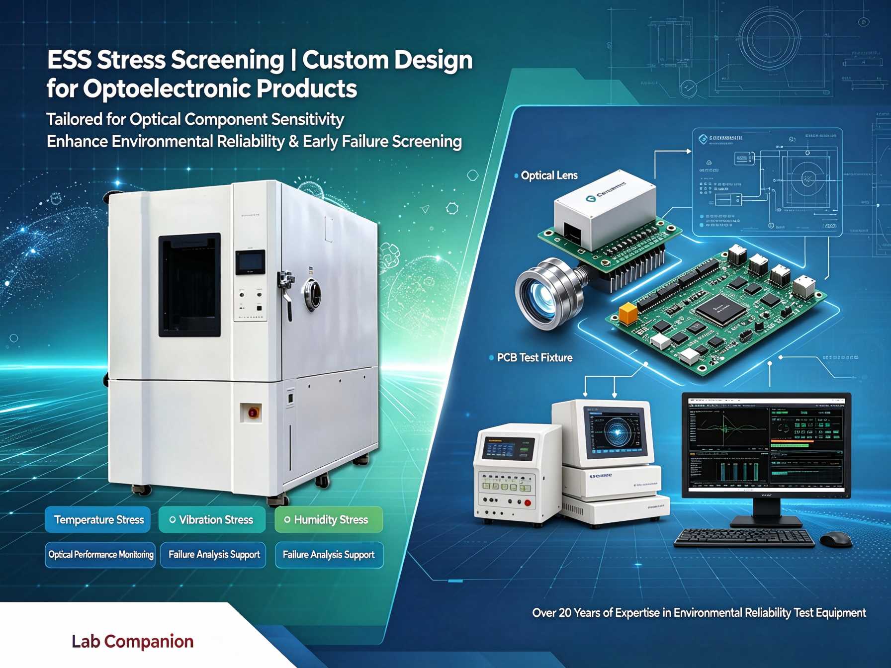
    Optoelectronic products such as optical modules and optical assemblies require both stable optical performance and electronic reliability. Their failures often manifest as optical performance degradation alongside structural defects. Environmental Stress Screening (ESS) before mass delivery is critical to weed out early failures and guarantee consistent optical performance. Given the high sensitivity of optical components to thermal disturbance, the ESS screening plan for optoelectronic products cannot be directly adopted from that for ordinary electronic devices. Rooted in the intelligent manufacturing base in Dongguan, Lab Companion has specialized in environmental reliability test equipment for over two decades. We provide tailored ESS stress screening solutions for the optical communication and optics industries. This article starts with failure mechanisms and outlines key considerations for ESS screening of optoelectronic products. 1. Typical Failure Mechanisms of Optoelectronic Products 1.1 Optical Performance Is Vulnerable to Thermal Stress The optical engine is highly sensitive to temperature changes. Thermal stress triggers wavelength shift and optical power fluctuation, directly degrading signal transmission quality. This is the core difference between optoelectronic devices and pure electronic components. 1.2 Thermal Fatigue of Interconnections and Packaging Lasers, photodetectors and high-speed circuits feature intricate interconnection structures. Under temperature cycling, mismatched Coefficients of Thermal Expansion (CTE) among different materials accumulate thermo-mechanical stress, which easily causes solder joint fatigue and package cracking. 1.3 Misalignment of Optical Paths and Microstructure Instability Optical assemblies rely on micron-level alignment precision. Deformation induced by temperature variation leads to optical misalignment and microstructure damage, which reduces optical indicators. Such damage is often latent and hard to detect in advance. 2. Core Requirements for ESS Screening of Optoelectronic Products 2.1 Linear and Controlled Temperature Ramp to Avoid Misjudgment of Optical Performance ESS for optoelectronics demands smooth temperature transition. Temperature overshoot and internal condensation must be prevented. Temperature overshoot instantly disturbs key indicators including optical power and wavelength; condensation corrodes optical end faces and circuits, introducing non-genuine failures and skewing screening results. Steady and linear temperature ramp is the foundation of optoelectronic ESS. 2.2 Compliance with Authorized Industry Specifications Reliability screening for optical communication components generally follows standards such as GR-468-CORE. Clear requirements are defined for temperature range, ramp rate, cycle count and dwell time. Equipment specifications must meet these standard requirements. 2.3 Adaptation to Mass Production Screening The optical communication industry features large shipment volumes. Production-line ESS needs simultaneous testing of multiple devices. The equipment shall support batch loading to match production tact time and improve screening coverage and efficiency. 3. Lab Companion ESS Stress Screening Solution for Optoelectronics 3.1 Wide Temperature Range with Multiple Linear Ramp Rates Standard models cover a temperature range from -70℃ to +150℃, with optional ramp rates of 5℃/min, 10℃/min and 15℃/min to suit different screening specifications for optical devices. 3.2 High-Precision Temperature Control and Uniform Thermal Field Temperature fluctuation ≤ ±0.3℃, temperature deviation ≤ ±2℃. Excellent internal thermal consistency ensures all samples in the same batch are exposed to identical thermal stress, delivering comparable and repeatable screening results. 3.3 Batch Loading & Full-Process Data Traceability Multi-layer sample racks are available for simultaneous testing of large batches of optoelectronic devices. The system automatically archives temperature profiles and test logs to satisfy quality control and traceability compliance requirements in the optical communication industry. 3.4 Flexible Customization Customizable chamber volume, temperature ramp rate, independent thermal zones and external data acquisition interfaces are available according to product dimensions and test conditions, catering to diverse test demands of optical modules and optical assemblies. 4. Equipment Selection Guide for Mass-Production ESS 4.1 Define Screening Parameters against Standards Determine the temperature range, ramp rate and cycle count based on specifications such as GR-468-CORE. Select equipment with adequate performance margin instead of operating continuously at full load. 4.2 Prioritize Linear Ramp and Anti-Condensation Performance Optoelectronic devices are sensitive to thermal shock. Focus on evaluating linear temperature ramp capability, anti-condensation design and thermal uniformity to avoid misjudgment caused by abnormal thermal disturbance. 4.3 Match Loading Configuration with Production Capacity For mass screening, prioritize models compatible with multi-layer racks and suitable chamber size to match production output and maximize sample quantity per test run. 4.4 Full-Cycle Technical Support Choose manufacturers with in-house manufacturing capacity and a sound service network. Reliable support covering installation, commissioning and calibration helps smooth the verification process for mass production of optoelectronic products. Conclusion The reliability of optoelectronic products stands for dual stability of optical performance and electronic structures. Based in Dongguan, Lab Companion delivers ESS stress screening solutions featuring wide temperature range, high-precision linear temperature ramp, stable thermal field, batch testing and full traceability, safeguarding the long-term stable operation of optical devices. Going forward, Lab Companion will keep focusing on environmental reliability test equipment and continuously empower reliability upgrading of the optical communication and optics industries.
    続きを読む
  • Lab Companion Custom Thermal Cycling Chamber: Customization Path for Temperature Range, Internal Volume & Dimensions, Temperature Ramp Rate and Special Functions
    Oct 16, 2026
    I. Necessity of Non-Standard Customization 1.1 Performance Limits of Standard Models Thermal cycling chambers serve as core equipment for reliability testing in electronics, semiconductors, automotive electronics, new energy and other industries. Lab Companion TC series standard thermal cycling chambers feature a standard temperature range of -70℃ to +150℃, with 5 selectable temperature ramp rates from 5℃/min to 25℃/min. Available internal volumes range from 34L up to 16,000L. Popular standard sizes including 80L, 150L, 225L, 408L and 800L are kept in stock. These configurations meet most conventional thermal cycling test requirements. Nevertheless, standard models have inherent performance boundaries. They cannot directly support test tasks when test specimens exceed the inner chamber size, when required test temperature limits go beyond the standard range, when samples need power-on operation or connection to data acquisition systems, or when tests involve flammable and explosive specimens requiring special protection. 1.2 Practical Scenarios for Non-Standard Customization Non-standard customization is not an optional add-on, but a prerequisite to valid testing execution. Typical application scenarios are listed below: New energy vehicle battery pack testing: full battery packs require testing covering -40℃ cold start and 85℃ high-temperature cycling; Semiconductor chip testing: demand for infinitely adjustable ramp rates from 1℃/min to 20℃/min to match different phases of chip testing; High heat-load testing: operating samples may generate heat up to tens of kilowatts. Standard chambers lack sufficient cooling capacity to maintain specified ramp rates under loaded conditions. Founded in 2005 and headquartered in Dongguan, Guangdong, Lab Companion is a National High-Tech Enterprise and Guangdong Provincial Specialized & Sophisticated Enterprise. With over 20 years of expertise in environmental reliability test equipment, we operate three R&D and manufacturing bases in Dongguan, Kunshan and Chongqing. We have established a full-cycle customization system covering requirement evaluation, design, production and delivery. II. Four Core Customization Dimensions for Lab Companion Thermal Cycling Chambers 2.1 Temperature Range Customization The baseline temperature range of standard TC chambers is -70℃ ~ +150℃. For aerospace and other special test applications, the low limit can be extended down to -100℃, while the upper temperature limit can reach +250℃. We have delivered proven custom units with a precise range of -78℃ ~ +150℃ to comply with GJB 150.5A military environmental test specifications. For combined temperature & humidity testing, integrated solutions covering 20%RH ~ 98%RH are available. 2.2 Internal Volume & Dimension Customization Chamber size is the most frequently requested custom item. Custom volumes from 80L to 8,000L can be engineered as requested. Our walk-in chambers start at 1,000L up to 10,000L, with further scaling available upon request. Inner chamber design takes full account of specimen outer dimensions, loading arrangement (single / multiple samples), material access methods (handcart, forklift, hoisting) and requirements for powered sample testing. Lab Companion once delivered a 20m³ extra-large custom chamber for an aerospace research institute to solve reliability testing challenges for large aerospace assemblies. Note: Standard models of 80L, 150L, 225L, 408L and 800L are in stock. 2.3 Temperature Ramp Rate Customization Standard chambers offer 5 fixed ramp rates: 5, 10, 15, 20 and 25℃/min. Customised ramp profiles can be developed per test specifications. For semiconductor projects, we have realised infinitely adjustable ramp rates from 1℃/min to 20℃/min to accommodate varied heating/cooling requirements across chip test phases. 2.4 Special Function Customization Optional dedicated functions can be integrated according to test workflows: Semiconductor applications: Nitrogen purge to prevent condensation on samples at low temperatures; High heat-load applications: dedicated thermal load matching solution to stabilise ramp rates under loaded conditions; Control & communication: RS485 and Ethernet as standard; optional OPC UA and Modbus TCP for MES connection. For semiconductor production lines, SECS/GEM protocol can be customised to enable seamless data exchange between test chambers and factory management systems; Additional options: remote monitoring, probe station interfaces and integrated data acquisition systems. III. Delivery Workflow from Requirement to Commissioning 3.1 In-depth Requirement Analysis & Technical Alignment The project starts with multiple rounds of technical discussion. Our engineers identify not only what needs testing, but also test purposes and acceptance targets. Combining test standards, specimen characteristics, test cycles and on-site factory conditions, we translate customer requirements into quantifiable technical specifications. 3.2 Concept Design & Proposal Confirmation Preliminary equipment design is generated based on requirement analysis. Core parameters to be finalised include temperature range, ramp rate profile, inner chamber dimensions, structural layout, fixture & electrical interfaces and control system functions. The proposal will undergo technical review and confirmation with customers to ensure equipment specifications fully match test demands. 3.3 Manufacturing & Factory Acceptance Testing Once the proposal is approved, production commences. Our three manufacturing bases achieve an annual capacity of more than 2,000 units. Standard models are delivered within 7–15 working days, while non-standard custom chambers can be finished within 20 working days. Before shipment, both no-load and loaded performance verifications are completed. 3.4 On-site Acceptance & Operational Training After equipment arrival, we perform installation, commissioning and on-site acceptance. Acceptance items cover temperature range and ramp rate under no-load conditions, ramp stability under loaded conditions, temperature uniformity & fluctuation, program cycle validation, communication and data acquisition verification. We also provide on-site operation training and maintenance support to secure long-term stable operation. IV. Manufacturing & Service Capabilities for Custom Thermal Cycling Chambers 4.1 Production Capacity at Dongguan Manufacturing Base The Dongguan headquarters serves as our R&D centre and primary production site for TC series chambers, with a plant area of 27,286 m² and an annual output of around 1,000 environmental test chambers. Products hold EU CE certification. Supported by the complete supply chain in the Greater Bay Area, R&D, component procurement, assembly and factory calibration are completed locally to shorten lead times. 4.2 Nationwide Service Network Sales and after-sales service centres are located in Beijing, Shanghai, Wuhan, Chengdu, Chongqing, Xi’an and Hong Kong, forming a nationwide service network with fast response for customers in the Pearl River Delta. The company operates under ISO9001, ISO14001, ISO45001 and ISO27001 management systems. The Lab Companion trademark is registered under the Madrid System, with trademark protection across 27 EU member states, UK, Canada and multiple Southeast Asian countries. 4.3 Core Hardware & Control System TC series chambers adopt cascade refrigeration with compressors from top international brands. Lab Companion’s proprietary cold balance energy-saving control technology eliminates energy waste caused by conventional simultaneous heating and cooling conflict. The controller is our self-developed C100 PID + fuzzy logic temperature & humidity control system, equipped with a colour touchscreen. It supports multi-segment programming, automatic data logging, report generation, network connection, remote monitoring and cluster management. V. Selection & Acceptance Guidelines for Non-Standard Custom Chambers 5.1 Technical Agreement Confirmation The technical agreement is the primary acceptance document for custom equipment. It must clearly define: temperature range, ramp rates (specifying no-load / loaded conditions), inner chamber dimensions and tolerances, temperature uniformity & fluctuation, communication protocols and data storage formats. For special functions such as nitrogen purge, thermal load adaptation and explosion-proof protection, implementation methods and acceptance criteria must be documented. 5.2 Acceptance Test Items Key on-site acceptance tests: Measured ramp rates under no-load conditions; Ramp rate stability verification under loaded conditions; Multi-point measurement of chamber temperature uniformity; Validation of cyclic test programs; Communication connection and data export verification. Third-party calibration in accordance with JJF 1101-2019 is recommended, with a CNAS-accredited calibration report issued. 5.3 Lead Time & After-sales Support Standard models: 7–15 working days delivery. Non-standard custom chambers: within 20 working days. Operation training and maintenance service are provided after acceptance. The equipment integrates multi-level safety alarms for overtemperature, compressor overload and fan failure to support long-duration continuous thermal cycling tests. VI. Conclusion The core value of non-standard custom thermal cycling chambers lies in the paradigm shift from “adapting tests to equipment” to “tailoring equipment for your tests”. Customised design ensures every equipment parameter precisely matches customer products, test standards and production workflows. Lab Companion TC thermal cycling chambers are built upon standard specifications: -70℃ ~ +150℃ temperature range, 5–25℃/min five-level ramp rates and 34L–16,000L volume coverage. Extended customization covers temperature range, chamber dimensions, ramp rate and dedicated special functions. Backed by Dongguan manufacturing capacity and nationwide service network, we deliver complete reliability test solutions from standard units to bespoke custom chambers for semiconductor, automotive electronics, new energy and aerospace industries. Detailed technical specifications and configurations can be further discussed according to actual test requirements.
    続きを読む

1 2 8 9 10 11 12 13 14 15 16 17
合計17ページ

伝言を残す

伝言を残す
弊社の製品にご興味があり、詳細を知りたい場合は、こちらにメッセージを残してください。できるだけ早く返信させていただきます。
提出する

ホーム

製品

ワッツアップ

お問い合わせ