Sample Restrictions for All Models of Test Chambers
Nov 17, 2025
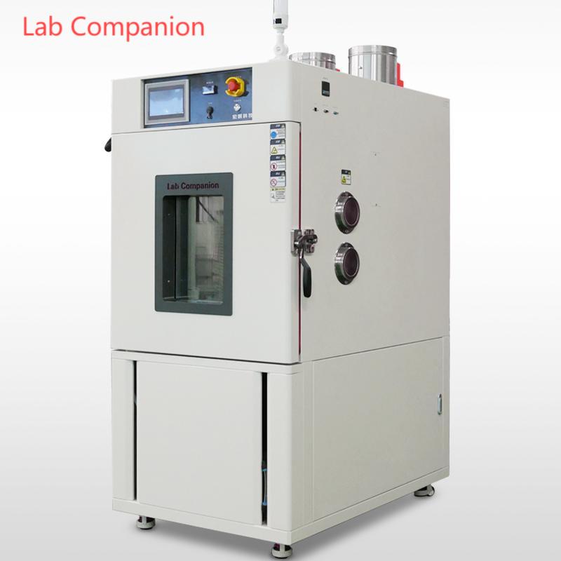
As core equipment in industrial production and scientific research that accurately simulates complex environmental conditions such as high and low temperatures, and humidity, the safe and stable operation of test chambers not only directly affects the test process, but is also closely related to the characteristics of test samples. To maximize the protection of the performance of the equipment's core components, avoid safety risks during operation, and ensure the accuracy and reliability of the final test data, all models of test chambers have established clear and strict restriction standards for sample selection. Testing and storage of the following models of samples are strictly prohibited.
The specific prohibited scope includes:
• Flammable substances such as gasoline and ethanol, explosive substances such as gunpowder and acetylene, and volatile substances such as methanol and ether;
• Corrosive substances such as strong acids, strong alkalis and various corrosive solvents that may damage the equipment cavity;
• Biological samples such as microorganisms, cell tissues and living organisms that may cause pollution or safety hazards;
• Samples that are strong electromagnetic emission sources such as high-frequency emission modules, which may interfere with the equipment's control system;
• Radioactive substances with radiation hazards such as uranium and cobalt;
• Highly toxic substances that pose serious hazards to humans and the environment, such as cyanides and highly toxic pesticides;
• All models of samples that may generate flammable, explosive, volatile, highly toxic, corrosive, or radioactive substances due to changes in temperature and humidity during the testing or storage process.
Before starting the test chamber, operators must confirm the specific properties of the samples through professional testing methods or authoritative materials, and strictly abide by the above restriction requirements. If there is any doubt in judging the applicability of the samples, they should consult the technical personnel of the equipment manufacturer or experts in related fields immediately, and must not operate blindly based on experience. This is to avoid equipment cavity damage, control system failure, safety accidents, or serious deviations in test data caused by illegal use.
続きを読む


 見積もりを依頼する


 IPv6ネットワークをサポート