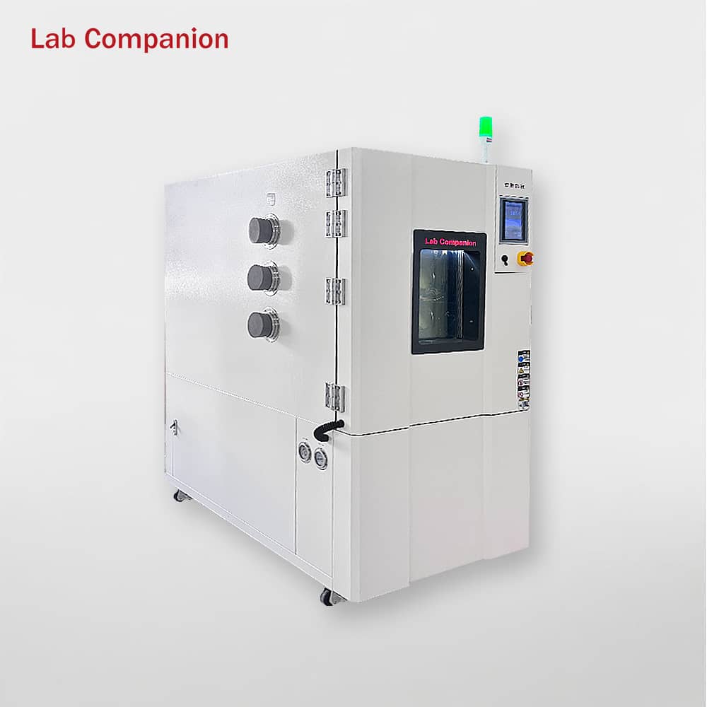
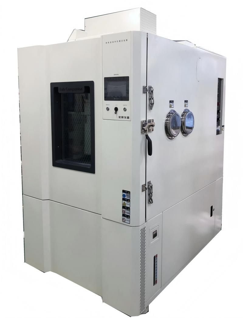
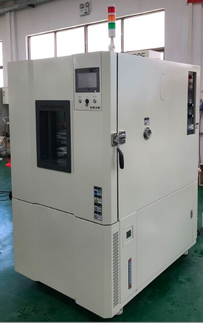
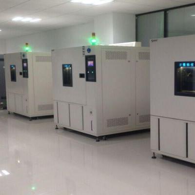
The precise environmental simulation capability of the temperature and humidity test chamber relies on a modular structure design of "chamber base + functional systems + control system". All components work in synergy to achieve accurate regulation and stable maintenance of temperature and humidity. The core structure is divided into the following parts:
I. Chamber Basic Structure: Core of Environmental Bearing
1. Inner Tank: As the core carrier of the test area, it is usually made of SUS 304 stainless steel for excellent corrosion resistance and easy cleaning. The smooth inner wall is equipped with one or two axial fans (quantity depends on test chamber volume), which circulate air inside the chamber to ensure uniform airflow distribution. For some models, the inner tank is treated with anti-condensation technology to prevent water dripping from affecting test results.
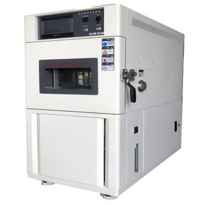
2. Outer Shell: Mainly constructed from galvanized steel sheets with electrostatic powder coating, it serves as protection and thermal insulation. The gap between the outer shell and inner tank is filled with dense mineral wool to minimize heat exchange between the inside and outside of the chamber, reducing energy consumption.
3. Chamber Door & Door Seal: The door is fitted with multi-layer heated glass, which allows real-time observation of test status; the heating and defrosting function prevents glass fogging. A silicone door seal is attached to the inner side of the door to ensure airtightness and avoid temperature/humidity leakage.
4. Shelves: Height-adjustable stainless steel shelves are designed for placing test samples. They ensure unobstructed air circulation around samples and do not interfere with internal airflow.
II. Temperature Control System
1. Heating Assembly: Installed near the air duct of the inner tank, it features electric heating tubes as the core component. With high temperature resistance and uniform heat generation, the tubes directly supply heat to the internal air and respond to heating commands from the controller.
2. Refrigeration System: Air conditioning components are integrated into the air handling system at the rear of the test chamber. Circulating air is cooled when passing through a heat exchanger. The condenser is generally air-cooled, with a water-cooled option available.
III. Humidity Control System
A. Humidification Device
l Electrode-type Humidifier: Consists of electrode rods and a humidification water tank (for storing distilled/deionized water). Steam is generated by heating the water when the electrode rods are energized.
B. Dehumidification Device
l Refrigeration Dehumidification Module: Linked with the evaporator, it achieves dehumidification through cooling and condensation.
l Drainage PipeCollects condensed water and discharges it outside the chamber to maintain inner tank dryness.
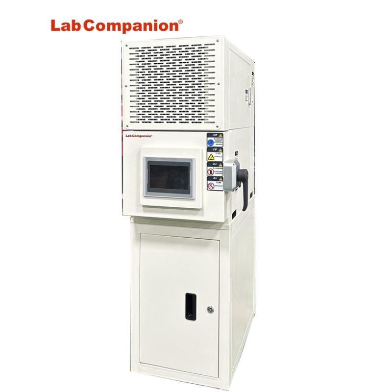
IV. Operation & Control System
1. Operators can send commands to the Labcompanion controller via the color LCD touchscreen to control the test chamber. Intuitive graphic symbols enable a user-friendly interface, simplifying operation without requiring additional instructions.
2. The Labcompanion controller is a self-monitoring, 32-bit digital measurement and control system specifically designed for test system applications.
Key Features
l Height-adjustable color LCD touchscreen for flexible operation.
l The program memory can store 100 test programs, with a total of up to 1000 program steps, supporting 250 program step cycles and 9999 program cycles.
l Software supports non-voltage input/output switches.
l Integrated temperature and humidity limit monitoring system.
l Connectable to host server systems via RS232-C serial interface or to network systems via TCP/IP.
l Switchable Chinese/English interface.
In summary, the structural design of the test chamber is centered on precision control, stable operation and reliability, with all components corresponding to the temperature/humidity control principles. Understanding the core components facilitates efficient equipment maintenance and troubleshooting.
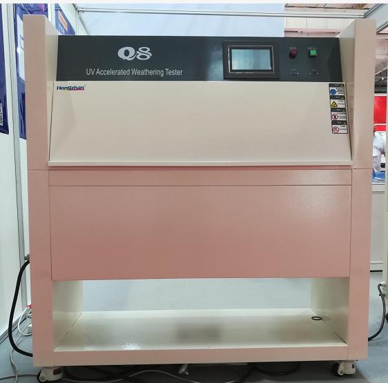
自然対流試験室、恒温恒湿試験室、高温オーブンの比較説明書:ホームエンターテイメントのオーディオビジュアル機器や自動車用電子機器は、多くのメーカーの主要製品の一つであり、開発プロセスでは、製品の温度に対する適応性とさまざまな温度での電子特性をシミュレートする必要があります。しかし、一般的なオーブンや温湿度チャンバーを使用して温度環境をシミュレートする場合、オーブンまたは温湿度チャンバーには循環ファンを備えたテストエリアがあるため、テストエリアで風速の問題が発生します。試験中、循環ファンを回転させることにより、温度均一性のバランスが保たれます。試験エリアの温度均一性は風の循環により達成できますが、試験対象製品の熱も循環空気によって奪われるため、無風使用環境(リビングルーム、屋内など)での実際の製品とは大きく異なります。風の循環の関係で、試験対象製品の温度差は10℃近くになります。実際の使用環境をシミュレートするため、多くの人が温度を生成できる試験室(オーブン、恒温恒湿室など)だけが自然対流試験を行えると誤解しています。実はそうではありません。仕様では風速に特別な要件があり、風速のない試験環境が必要です。自然対流試験装置とソフトウェアを通じて、ファンを通さない温度環境(自然対流)を生成し、試験対象製品の温度検出のための試験統合試験を行います。このソリューションは、家庭用電子機器や限られたスペースでの実際の周囲温度試験(大型液晶テレビ、自動車のコックピット、自動車用電子機器、ノートパソコン、デスクトップ、ゲーム機、ステレオなど)に使用できます。強制空気循環試験規格:IEC-68-2-2、GB2423.2、GB2423.2-89 3.31 風循環の有無による試験環境と試験対象製品の試験の違い:説明書:試験対象製品に通電されていない場合、試験対象製品自体は発熱せず、その熱源は試験炉内の空気熱を吸収するだけです。試験対象製品に通電して加熱すると、試験炉内の風循環が試験対象製品の熱を奪います。風速が1メートル増加するごとに、その熱は約10%減少します。エアコンのない屋内環境で電子製品の温度特性をシミュレートするとします。オーブンまたは恒温加湿器を使用して35℃をシミュレートする場合、電気加熱とコンプレッサーにより環境を35℃以内に制御できますが、オーブンと温湿試験チャンバーの風循環が試験対象製品の熱を奪います。そのため、試験対象製品の実際の温度は、実際の無風状態での温度よりも低くなります。実際の無風環境(屋内、無始動車のコックピット、計器シャーシ、屋外の防水チャンバーなど)を効果的にシミュレートするには、風速のない自然対流試験チャンバーを使用する必要があります。試験対象風速とIC製品の比較表:説明: 周囲の風速が速い場合、風のサイクルにより IC 表面温度も IC 表面の熱を奪い、結果として風速が速くなり、温度が低くなります。


 見積もりを依頼する


 IPv6ネットワークをサポート